
| Categories | Electric Generator Manuals, Home Appliance, Yamaha Generator Manuals |
|---|---|
| Tags | Yamaha EF2800i, Yamaha YG2800i |
| Download File |
|
| Document File Type | |
| Copyright | Attribution Non-commercial |
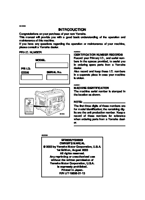
Generator OWNER’S MANUAL EF2800i YG2800i LIT-19626-01-13 7VU-28199-12 AE00002 INTRODUCTION Congratulations on your purchase of your new Yamaha. This manual will provide you with a good basic understanding of the operation and maintenance of this machine. If you have any questions regarding the operation or maintenance of your machine, please consult a Yamaha dealer. PRI-I.D. NUMBER: MODEL PRI-I.D. CODE AE00012 SERIAL No. IDENTIFICATION NUMBER RECORDS Record your Primary I.D., and serial numbers in the spaces provided, to assist you in ordering spare parts from a Yamaha dealer.
Power Equipment User Manual Free Download. Electric Generator for Power Manual. Free Manual Download PDF.
Also record and keep these I.D. numbers in a separate place in case your machine is stolen. AE00011 MACHINE IDENTIFICATION The machine serial number is stamped in the location as shown. NOTE: The first three digits of these numbers are for model identification; the remaining digits are the unit production number. Keep a record of these numbers for reference when ordering parts from a Yamaha dealer. 790-057a AE00022 EF2800i/YG2800i OWNER’S MANUAL 2003 by Yamaha Motor Corporation, U.S.A. 1st Edition, August 2003 Any reprinting or unauthorized use without the written permission of Yamaha Motor Corporation, U.S.A. is expressly prohibited. Printed in Japan. P/N LIT-19626-01-13 AE00032 w PLEASE READ AND UNDERSTAND THIS MANUAL COMPLETELY BEFORE OPERATING THE MACHINE. Particularly important information is distinguished in this manual by the following notations. NOTE: 9 Yamaha continually seeks advancements in product design and quality. Therefore, while this manual contains the most current product information available at the time of printing, there may be minor discrepancies between your engine and this manual. If there is any question concerning this manual, please consult your Yamaha dealer. 9 This manual should be considered a permanent part of this engine and should remain with this engine when resold. The Safety Alert Symbol means ATTENTION! BECOME ALERT! YOUR SAFETY IS INVOLVED! w Failure to follow WARNING instructions could result in severe injury or death to the engine operator, a bystander, or a person inspecting or repairing the engine. cC A CAUTION indicates special precautions that must be taken to avoid damage to the engine. NOTE: A NOTE provides key information to make procedures easier or clearer. AE00041 CONTENTS LIMITED WARRANTY (EF- AND EDL-SERIES) 1 LIMITED WARRANTY (EC- AND YG-SERIES) 2 LOCATION OF IMPORTANT LABELS 4 SAFETY INFORMATION 5 EXHAUST FUMES ARE POISONOUS .5 FUEL IS HIGHLY FLAMMABLE AND POISONOUS .5 ENGINE AND MUFFLER MAY BE HOT 5 ELECTRIC SHOCK PREVENTION .6 CONNECTION NOTES .7 CONNECTION .7 EXTENSION CORD NOTES .7 CONTROL FUNCTION .8 DESCRIPTION 8 CONTROL PANEL .8 OIL WARNING SYSTEM .10 ENGINE SWITCH 10 ECONOMY CONTROL SWITCH .10 DC PROTECTOR 11 G.F.C.I. RECEPTACLE (for YG2800i) .11 PRE-OPERATION CHECK .12 FUEL 12 ENGINE OIL 13 GROUND (Earth) .13 OPERATION .14 STARTING THE ENGINE 14 APPLICATION RANGE .16 CONNECTION .17 STOPPING THE ENGINE .21 PERIODIC MAINTENANCE .22 MAINTENANCE CHART .22 SPARK PLUG INSPECTION .24 CARBURETOR ADJUSTMENT .24 ENGINE OIL REPLACEMENT 25 MUFFLER SCREEN AND SPARK ARRESTER .26 AIR FILTER 28 FUEL COCK 29 FUEL TANK FILTER 29 G.F.C.I. RECEPTACLE TEST (for YG2800i) .30 TROUBLESHOOTING 31 STORAGE .33 DRAIN THE FUEL .33 ENGINE .33 EXHAUST EMISSION CONTROL SYSTEM AND COMPONENTS 34 SPECIFICATIONS 35 DIMENSIONS 35 ENGINE .35 GENERATOR 35 WIRING DIAGRAM .36 EF2800i 36 YG2800i .37 AE01119 YAMAHA MOTOR CORPORATION U.S.A. EF- AND EDL-SERIES GENERATOR LIMITED WARRANTY Yamaha Motor Corporation, U.S.A. hereby warrants that new Yamaha consumer generators purchased from an authorized Yamaha consumer generator dealer in the continental United States will be free from defects in material and workmanship for the period of time stated herein, subject to certain stated limitations. THE PERIOD OF WARRANTY Any new EFseries or EDL-series Yamaha Generator purchased for private, non-commercial use from an authorized Yamaha consumer generator dealer in the continental United States will be warranted against defects in material or workmanship for a period two (2) years from date of purchase, subject to exclusions noted herein. Any Yamaha non-commercial generator purchased and utilized for commercial or rental applications will be warranted for a period one (1) year from the date of purchase, subject to exclusions noted herein. DURING THE PERIOD OF WARRANTY any authorized Yamaha consumer generator dealer will, free of charge, repair or replace, at Yamaha’s option, any part adjudged defective by Yamaha due to faulty workmanship or material from the factory. Parts used in warranty repairs will be warranted for the balance of the product’s warranty period. All parts replaced under warranty become property of Yamaha Motor Corporation U.S.A. GENERAL EXCLUSIONS from this warranty shall include any failures caused by: a. Installation of parts or accessories that are not qualitatively equivalent to genuine Yamaha parts. b. Abnormal strain, neglect, or abuse. c. Lack of proper maintenance. d. Accident or collision damage. SPECIFIC EXCLUSIONS from this warranty shall include parts replaced due to normal wear or routine maintenance. THE CUSTOMER’S RESPONSIBILITY under this warranty shall be to: 1. Operate and maintain the generator as specified in the appropriate Owner’s Manual; 2. Give notice to an authorized Yamaha consumer generator dealer of any and all apparent defects within ten (10) days after discovery, and make the unit available at that time for inspection and repairs at such dealer’s place of business. WARRANTY TRANSFER: To transfer the warranty from the original purchaser to any subsequent purchaser(s), it is imperative that the unit be inspected and registered for warranty by an authorized Yamaha consumer generator dealer. In order for this warranty to remain in effect, this inspection and registration must take place within ten (10) days after transfer. An inspection and registration fee will be charged for this service. In no case will the warranty be extended beyond the original period. YAMAHA MOTOR CORPORATION, U.S.A. MAKES NO OTHER WARRANTY OF ANY KIND, EXPRESSED OR IMPLIED. ALL IMPLIED WARRANTIES OF MERCHANTABILITY AND FITNESS FOR A PARTICULAR PURPOSE WHICH EXCEED THE OBLIGATIONS AND TIME LIMITS STATED IN THIS WARRANTY ARE HEREBY DISCLAIMED BY YAMAHA MOTOR CORPORATION, U.S.A. AND EXCLUDED FROM THIS WARRANTY. SOME STATES DO NOT ALLOW LIMITATIONS ON HOW LONG AN IMPLIED WARRANTY LASTS, SO THE ABOVE LIMITATION MAY NOT APPLY TO YOU. ALSO EXCLUDED FROM THIS WARRANTY ARE ANY INCIDENTAL OR CONSEQUENTIAL DAMAGES INCLUDING LOSS OF USE. SOME STATES DO NOT ALLOW THE EXCLUSION OR LIMITATION OF INCIDENTAL OR CONSEQUENTIAL DAMAGES, SO THE ABOVE EXCLUSION MAY NOT APPLY TO YOU. THIS WARRANTY GIVES YOU SPECIFIC LEGAL RIGHTS, AND YOU MAY ALSO HAVE OTHER RIGHTS WHICH VARY FROM STATE TO STATE. YAMAHA MOTOR CORPORATION, U.S.A. Post Office Box 6555 Cypress, California 90630 1 YAMAHA MOTOR CORPORATION U.S.A. EC- AND YG-SERIES INDUSTRIAL GENERATOR LIMITED WARRANTY Yamaha Motor Corporation, U.S.A. hereby warrants that new Yamaha EC- and YG-series generators purchased from an authorized Yamaha industrial generator dealer in the continental United States will be free from defects in material and workmanship for the period of time stated herein, subject to certain stated limitations. THE PERIOD OF WARRANTY for Yamaha ECseries and YG-series generators shall be one (1) year from the date of purchase. DURING THE PERIOD OF WARRANTY any authorized Yamaha industrial generator dealer will, free of charge, repair or replace, at Yamaha’s option, any part adjudged defective by Yamaha due to faulty workmanship or material from the factory. Parts used in warranty repairs will be warranted for the balance of the product’s warranty period. All parts replaced under warranty become property of Yamaha Motor Corporation U.S.A. GENERAL EXCLUSIONS from this warranty shall include any failures caused by: a. Installation of parts or accessories that are not qualitatively equivalent to genuine Yamaha parts. b. Abnormal strain, neglect, or abuse. c. Lack of proper maintenance. d. Accident or collision damage. SPECIFIC EXCLUSIONS from this warranty shall include parts replaced due to normal wear or routine maintenance. THE CUSTOMER’S RESPONSIBILITY under this warranty shall be to: 1. Operate and maintain the diesel generator as specified in the appropriate Owner’s Manual; 2. Give notice to an authorized Yamaha industrial generator dealer of any and all apparent defects within ten (10) days after discovery, and make the unit available at that time for inspection and repairs at such dealer’s place of business. WARRANTY TRANSFER: To transfer the warranty from the original purchaser to any subsequent purchaser(s), it is imperative that the unit be inspected and registered for warranty by an authorized Yamaha industrial generator dealer. In order for this warranty to remain in effect, this inspection and registration must take place within ten (10) days after transfer. An inspection and registration fee will be charged for this service. In no case will the warranty be extended beyond the original period. YAMAHA MOTOR CORPORATION, U.S.A. MAKES NO OTHER WARRANTY OF ANY KIND, EXPRESSED OR IMPLIED. ALL IMPLIED WARRANTIES OF MERCHANTABILITY AND FITNESS FOR A PARTICULAR PURPOSE WHICH EXCEED THE OBLIGATIONS AND TIME LIMITS STATED IN THIS WARRANTY ARE HEREBY DISCLAIMED BY YAMAHA MOTOR CORPORATION, U.S.A. AND EXCLUDED FROM THIS WARRANTY. SOME STATES DO NOT ALLOW LIMITATIONS ON HOW LONG AN IMPLIED WARRANTY LASTS, SO THE ABOVE LIMITATION MAY NOT APPLY TO YOU. ALSO EXCLUDED FROM THIS WARRANTY ARE ANY INCIDENTAL OR CONSEQUENTIAL DAMAGES INCLUDING LOSS OF USE. SOME STATES DO NOT ALLOW THE EXCLUSION OR LIMITATION OF INCIDENTAL OR CONSEQUENTIAL DAMAGES, SO THE ABOVE EXCLUSION MAY NOT APPLY TO YOU. THIS WARRANTY GIVES YOU SPECIFIC LEGAL RIGHTS, AND YOU MAY ALSO HAVE OTHER RIGHTS WHICH VARY FROM STATE TO STATE. YAMAHA MOTOR CORPORATION, U.S.A. Post Office Box 6555 Cypress, California 90630 2 WARRANTY QUESTIONS AND ANSWERS Q. What costs are my responsibility during the warranty period? A. The customer’s responsibility includes all costs of normal maintenance service, nonwarranty repairs, accident damages, as well as oil and spark plugs. Q. What are some examples of “abnormal ” strain, neglect, or abuse? A. These terms are general and overlap each other in areas. Specific examples include: Running the machine out of oil; lack of proper maintenance; operating the machine with a broken or damaged part which causes another part to fail; and so on. If you have any specific questions on operation or maintenance, please contact your dealer for advice. Q. Does the warranty cover incidental costs such as transportation due to a failure? A. No. The warranty is limited to repair of the machine itself. Q. May I perform any or all of the recommended maintenance shown in the Owner’s Manual instead of having the dealer do them? A. Yes, if you are a qualified mechanic and follow the procedures specified in the Owner’s and Service Manual. We do recommend, however, that items requiring special tools or equipment be done by a Yam …..
the upper level. q 1 Upper level 700-006a 0°C 25°C A YAMALUBE 4(10W-30) D SAE 10W C SAE #20 B SAE #30 Recommended oil: å YAMALUBE 4 (10W-30) or SAE 10W-30 type SE motor oil SAE #30 ç SAE #20 SAE 10W Engine oil quantity: 0.6 L (0.53 Imp qt, 0.63 US qt) NOTE: Recommended engine oil classification: API Service “SE ” or “SF “. 32°F 80°F 700-065 cC Be sure no foreign material enters the crankcase. 25 AE00443 MUFFLER SCREEN AND SPARK ARRESTER w The engine and muffler will be very hot after the engine has been run. Avoid touching the engine and muffler while they are still hot with any part of your body or clothing during inspection or repair. 1. Remove the muffler screen. 1 Screen 2 Screw 711-067 741-001 q w 2. Use a flathead screw driver to pry the spark arrester out from the muffler. 711-054c 3. Remove the spark arrester. q 1 Spark arrester 711-054e 4. Remove the carbon deposits on the muffler screen and spark arrester using a wire brush. cC When cleaning, use the wire brush lightly to avoid damaging or scratching of the muffler screen and spark arrester. 5. Check the muffler screen and spark arrester. Replace them if damaged. 711-022 711-050 26 w q 6. Install the spark arrester. NOTE: Align the spark arrester projection with the hole in the muffler pipe. 711-054d 1 Projection 2 Hole 7. Install the muffler screen. 711-067a 27 AE00451 AIR FILTER 1. Remove the air filter cover and element. 2. Wash the element in solvent and dry. 3. Oil the element and squeeze out excess oil. The element should be wet but not dripping. Recommended oil: Foam-air-filter oil or SAE #20 motor oil cC Do not wring out the element. This could cause it to tear. 4. Insert the element into the air filter. NOTE: Be sure the element sealing surface matches the air filter so there is no air leak. 710-037a cC The engine should never run without the element; excessive piston and cylinder wear may result. w Never use solvent while smoking or in the vicinity of an open flame. 28 AE00461 FUEL COCK w Never use or be near fuel and solvent while smoking or in the vicinity of an open flame. 1. 2. 3. 4. 5. 6. Stop the engine. Turn the fuel cock lever to “OFF “. Remove the fuel cock cup and gasket. Clean the cup with solvent and wipe it off. Check the gasket. Replace it if damaged. Reinstall the gasket and fuel cock cup. w Be sure the fuel cock cup is tightened securely. 705-065a AE00471 FUEL TANK FILTER 1. Remove the fuel tank cap and filter. q 1 Filter 2. Clean the filter with solvent. If damaged, replace. 3. Wipe the filter and insert it. w Be sure the tank cap is tightened securely. 707-082 29 AE01007 q w 763-105 G.F.C.I. RECEPTACLE TEST (for YG2800i) 1. Start the engine. 2. Press the test button 1, then check the position of the reset button 2. G.F.C.I. Reset Button Position after Test Pop Out 3 Stay In 4 763-059 3 4 G.F.C.I. Receptacle Operation Correct Incorrect 3. If G.F.C.I. operation is correct, push in the reset button. If the G.F.C.I. operates incorrectly, consult a Yamaha dealer. w Do not operate the generator with a faulty G.F.C.I. circuit. Electric shock could occur. Have the generator repaired by a qualified mechanic. 30 AE00512 TROUBLESHOOTING Engine won’t start 1. Fuel systems No fuel supplied to combustion chamber. 2 No fuel in tank Supply fuel. 2 Clogged fuel line Clean fuel line. 2 Foreign matter in fuel cock Clean fuel cock. 2 Clogged carburetor Clean carburetor. 707-001 705-037a 2. Engine oil system Insufficient 2 Oil level is low Add engine oil. 700-006 3. Electrical systems 2 Engine switch to “ON “. Poor spark 2 Spark plug dirty with carbon or wet Remove carbon or wipe spark plug dry. 2 Faulty ignition system Consult dealer. 763-084i 4. Compression Insufficient 2 Worn out piston and cylinder Consult dealer. 2 Loose cylinder head nuts Tighten nuts properly. 2 Damaged gasket Replace gasket. 760-009 AE00785 Generator won’t produce power 2 Safety device (AC) to “OFF ” Stop the engine, then restart. 2 Safety device (DC protector) to “OFF ” Press to reset the DC protector. 31 AE00515 A ENGINE DOES NOT START B Turn the engine switch to “ON “, then pull the recoil starter and check if the oil warining light flickers. E Check engine oil level. C Does not flicker D Flickers. F OK Consult a Yamaha dealer. G Level low Add engine oil. H Pull the recoil starter and check the spark plug for spark strength. (See “WARNING “) K Check the spark plug. 9 Type: 9 Gap: w 9 To prevent FIRE HAZARDS be sure fuel is not present in the spark plug area. 9 To prevent FIRE HAZARDS be sure to place the spark plug as far way as possible from the spark plug hole and carburetor area. 9 To prevent ELECTRIC SHOCK do not hold spark plug lead with hand while testing. I Engine does not start. J Engine starts. L Incorrect Replace or Adjust Gap. M OK Clean the spark plug. N Check the following O Clogged 9 Fuel cock clogging 9 Air cleaner element P OK clogging. 32 Q Clean or Replace; Consult a Yamaha dealer. Consult a Yamaha dealer. R AE00601 q STORAGE Long term storage of your machine will require some preventive procedures to guard against deterioration. AE00611 a w DRAIN THE FUEL 1. Drain the fuel tank, fuel cock, and carburetor float bowl. a Carburetor drain plug e r 2. Pour a cup of SAE 10W30 or 20W40 motor oil into the tank. 3. Shake the tank to coat the inner surfaces thoroughly. 4. Drain off the excess oil. 707-083 AE00621 ENGINE 1. Remove the spark plug, pour about one tablespoon of SAE 10W30 or 20W40 motor oil into the spark plug hole and reinstall the spark plug. Recoil start the engine by turning over several times (with ignition off) to coat the cylinder walls with oil. 2. Pull the recoil starter until you feel compression. Then stop pulling. (This prevents the cylinder and valves from rusting). 3. Clean exterior of the generator and apply a rust inhibitor. 4. Store the generator in a dry, well-ventilated place, with the cover placed over it. 5. The generator must remain in a vertical position when stored, carried or operated. 712-010 33 AE01002 EXHAUST EMISSION CONTROL SYSTEM AND COMPONENTS Item Acronym 9 CARB. ASSY., LH. & JT., .CARB (Carburetor) CARBURETOR2 9 C.D.I. UNIT ASSY. & C.D.I EI (Electronic Ignition) MAGNETO ASSY. & PLUG, SPARK 9 CRANKCASE1 & HEAD, PCV (Positive Crankcase CYLINDER1 Ventilation) 9 AIR FILTER ASSY. .ACL (Air Cleaner) 9 MUFF., 2, CAP, NET, WIRE2 & ARRESTER, SPARK The above items and the corresponding acronyms are provided in accordance with U.S. EPA REGULATIONS FOR NEW NONROAD SPARK-IGNITION NONHANDHELD ENGINES and the CALIFORNIA REGULATIONS FOR 1995 AND LATER SMALL OFF-ROAD ENGINES. The acronyms conform to the latest version of the SAE’s recommended practice document J1930, “Diagnostic Acronyms, Terms, and Definitions For Electrical/Electronic System “. It is recommended that these items be serviced by a Yamaha dealer. 34 AE00701 SPECIFICATIONS AE00702 DIMENSIONS Overall Length Overall Width Overall Height Dry Weight Unit mm (in) mm (in) mm (in) kg (lb) EF2800i/YG2800i 487 (19.2) 395 (15.6) 425 (16.7) 29 (63.9) AE00704 ENGINE Unit Type Cylinder Arrangement Displacement Bore × Stroke Rated Output Operation Hours Fuel Fuel Tank Capacity Engine Oil Quantity Ignition System Spark Plug: Type Spark Plug: Gap Noise Level* EF2800i/YG2800i Forced air cooled 4-stroke gasoline OHV Inclined, 1 cylinder 171 66.0 × 50.0 (2.60 × 1.97) 3.3 (4.4)/3,600 7.7 Unleaded gasoline 11.2 (2.46, 2.96) 0.6 (0.53, 0.63) CDI BPR4ES (NGK) 0.70.8 (0.0280.031) 67 cm3 mm (in) kW(HP)/r/min Hr L (Imp gal, US gal) L (Imp qt, US qt) mm (in) dB (A) * : Measured at rated operation from 7 m (23 ft) distance. AE00707 GENERATOR Unit AC Output Rated Voltage Rated frequency Rated current Rated Output Safty Device: Type DC Output Rated voltage Rated current Safety Device: Type V Hz A kVA EF2800i/YG2800i 120 60 20.8 2.5 Electronic 12 10 DC protector 35 V A AE00751 WIRING DIAGRAM EF2800i q Br Br Y Y Y Y Y Y Y Y Y R W B R R Br R R y t R R y y G/Y G/Y R Br w L L L L eG Y R L R G/Y BR r B Gy Br R Y O R B Y B/W O O R B Y B/W O O B i G/Y Y u o w w G/Y O R O O G/Y R O B/W R B B !0 !1 R R Y !9 G/Y B/W !8 R G/Y B/W (B) G/Y W/LB/W G/Y W/LB/W (R) R R Y L R Y L B/W L W/L B !2 !3 @0 G Y R L O R G/Y B/W B/W G/Y G/Y B/W !4 !6 !7 B !5 1 Main coil 2 Sub coil 3 DC rectifier 4 Control unit 5 AC pilot light 6 AC receptacle 7 Ground (Earth) terminal 8 Economy control switch 9 Overload indicator light 0 DC receptacle q DC protector (breaker) w Engine switch e Oil warning light r Oil warning unit t Oil level gauge y Ignition coil u Spark plug i AC-CDI unit o Pulser coil p Stepping motor 36 Color code B Black Br Brown G Green Gy Gray L Blue O Orange R Red W White Y Yellow B/W Black/White G/Y Green/Yellow W/L White/Blue AE00751 WIRING DIAGRAM YG2800i q u Br Br Y Y Y Y Y Y Y Y Y R W B R R Br R R Br y G/Y R t R G/Y R B w L L L L eG Y R L R G/Y BR r o B Gy Br R Y O R B Y B/W O O R B Y B/W O O Y i G/Y w w G/Y O R O O G/Y O R !0 B/W R B B 1!1 !2 R R Y @0 G/Y B/W !9 R G/Y B/W (B) G/Y W/L B/W G/Y W/L B/W (R) R R Y L R Y L B/W L W/L B !3 !4 @1 G Y R L O R G/Y B/W B/W G/Y G/Y B/W !5 !7 !8 B !6 1 Main coil 2 Sub coil 3 DC rectifier 4 Control unit 5 AC pilot light 6 AC receptacle 7 G.F.C.I. receptacle 8 Ground (Earth) terminal 9 Economy control switch 0 Overload indicator light q DC receptacle w DC protector (breaker) e Engine switch r Oil warning light t Oil warning unit y Oil level gauge u Ignition coil i Spark plug o AC-CDI unit p Pulser coil a Stepping motor 37 770-038b Color code B Black Br Brown G Green Gy Gray L Blue O Orange R Red W White Y Yellow B/W Black/White G/Y Green/Yellow W/L White/Blue PRINTED ON RECYCLED PAPER PRINTED IN JAPAN 03 9 08 0.3 × 1 ! …
Wikipedia’s page for Yamaha
Publisher: www.yamahagenerators.com