| Categories | Carrier HVAC Manuals, HVAC Heating Ventilating Air Conditioning Manuals |
|---|---|
| Tags | Carrier 58MVP |
| Download File |
|
| Language | English |
| Product Brand | Support Phone Number: In North America, please call 1-800-CARRIER for immediate customer assistance from 8:00a -5:00p (EST) weekdays, Heating, Ventilating and Air Conditioning - HVAC |
| Document File Type | |
| Publisher | corp.carrier.com |
| Wikipedia's Page | Carrier Corporation |
| Copyright | Attribution Non-commercial |
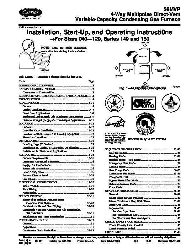
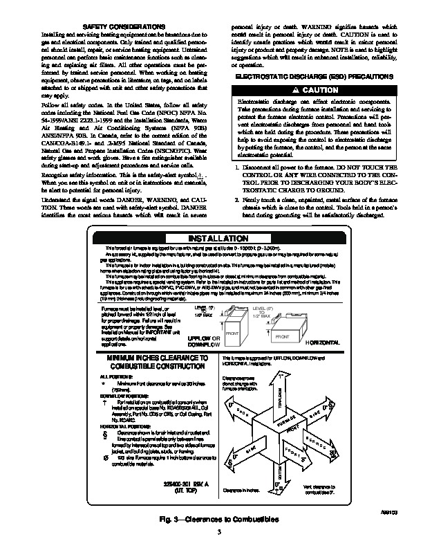
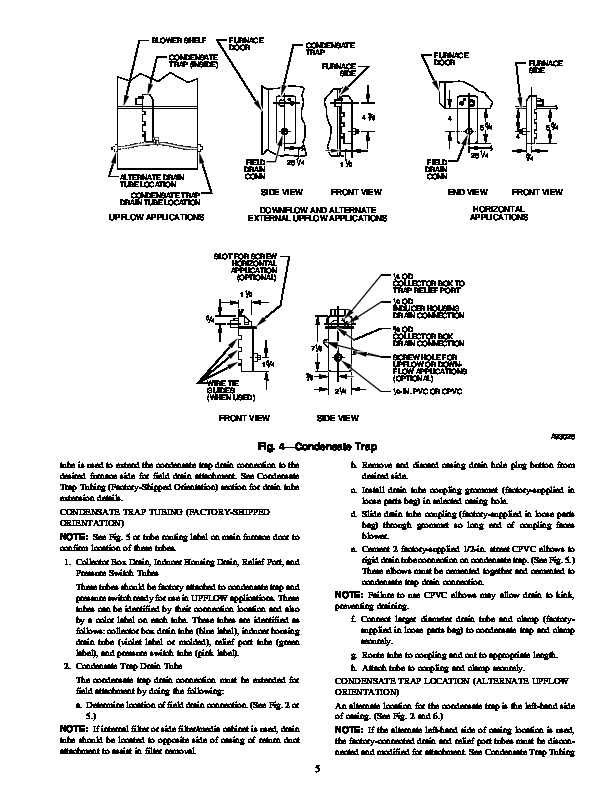
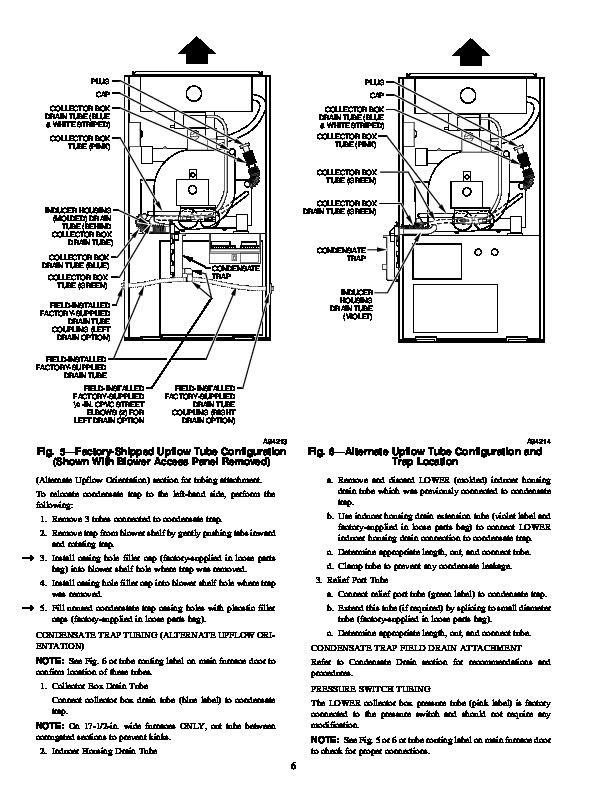
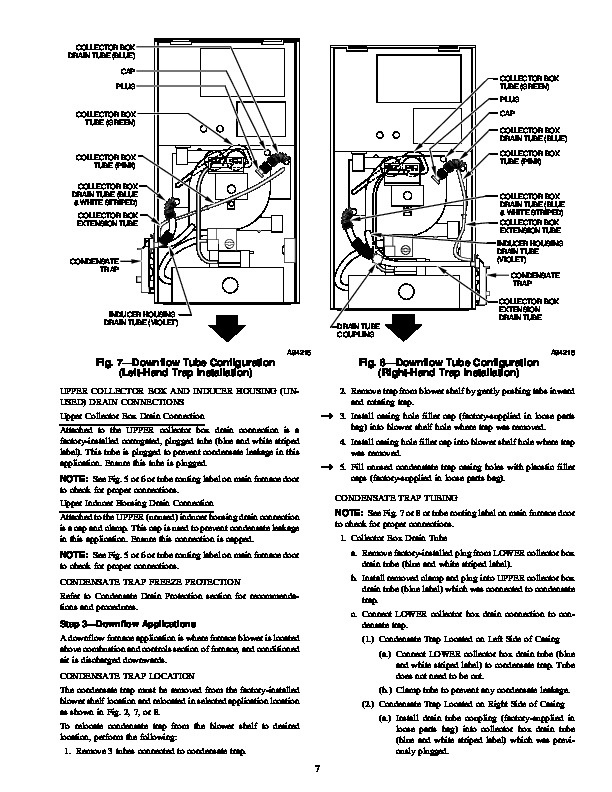
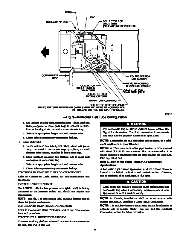
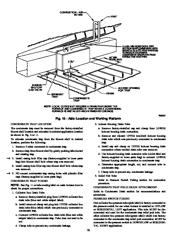
58MVP 4-Way Multipoise Direct-Vent Variable-Capacity Condensing Gas Furnace Visit www.carrier.com Installation, Start-Up, and Operating Instructi0ns For Sizes 040–120, Series 140 and 150 AIRFLOW NOTE: Read the entire instruction manual before starting the installation. UPFLOW A93040 HORIZONTAL LEFT DOWNFLOW AIRFLOW HORIZONTAL RIGHT AIRFLOW This symbol indicates a change since the last issue. Index Page DIMENSIONAL DRAWING 2 SAFETY CONSIDERATIONS .3 Clearances to Combustibles 3 ELECTROSTATIC DISCHARGE (ESD) PRECAUTIONS 3-4 INTRODUCTION 4 APPLICATIONS 4-11 General 4 Upflow Applications 4-7 Downflow Applications .7-8 Horizontal Left (Supply-Air Discharge) Applications .8-9 Horizontal Right (Supply-Air Discharge) Applications .9-11 LOCATION 11-13 General .11-12 Low-Fire Only Installation 12-13 Furnace Location Relative to Cooling Equipment 13 Hazardous Locations .13 INSTALLATION 13-15 Leveling Legs (If Desired) .13 Installation In Upflow or Downflow Applications 13-15 Installation In Horizontal Applications 15 AIR DUCTS 15-18 General Requirements .15-16 Ductwork Acoustical Treatment .16 Supply Air Connections 16 Return Air connections .16 Filter Arrangement 16 Bottom Closure Panel 16-18 Gas Piping .18 ELECTRICAL CONNECTIONS .18-20 115-v Wiring 18-19 24-v Wiring 19-20 Accessories 20 DIRECT VENTING .20-31 Removal of Existing Furnaces from Common Vent Systems 20-22 Combustion-Air and Vent Piping .22-28 Concentric Vent and Combustion-Air Termination Kit Installation 28-31 Multiventing and Vent Terminations .31 CONDENSATE DRAIN 31-33 General 31 Application 31 Condensate Drain Protection .31-33 AIRFLOW Fig.
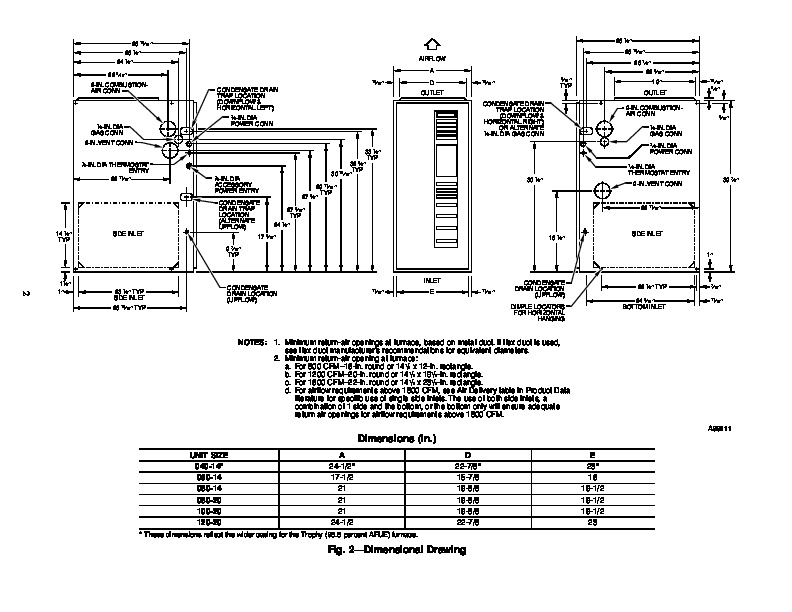
1–Multipoise Orientations A93041 ama CERTIFIED As an ENERGY STAR® Partner, Carrier Corporation has determined that this product meets the ENERGY STAR® guidelines for energy efficiency. REGISTERED QUALITY SYSTEM SEQUENCE OF OPERATION 33-36 Self-Test Mode 33 Heating Mode 33-34 Heating Mode–Two Stage 34 Emergency Heat Mode .34 Cooling Mode .34 Heat Pump Mode .34-35 Continuous Fan Mode .35-36 Component Test 36 Bypass Humidifier Mode 36 Dehumidification Mode 36 Zone Mode 36 START-UP PROCEDURES 36-45 General .36-37 Select Setup Switch Positions 37 Prime Condensate Trap With Water .37-38 Purge Gas Lines 38 Adjustments .38-45 Set Gas Input Rate .38-44 Set Temperature Rise 44 Set Thermostat Heat Anticipator 45 CHECK SAFETY CONTROLS 45 Check Primary Limit Control .45 Check Pressure Switch .45 CHECKLIST .45-46 Manufacturer reserves the right to discontinue, or change at any time, specifications or designs without notice and without incurring obligations. Book 1 4 PC 101 Catalog No. 535-786 Printed in U.S.A. Form 58MVP-10SI Pg 1 10-00 Replaces: 58MVP-9SI Tab 6a 8a 26 15/16 ” 26 1/4 ” 24 1/2 ” 22 5/16 ” 13/16 ” 28 1/2 ” 26 15/16 ” AIRFLOW A D OUTLET CONDENSATE DRAIN TRAP LOCATION (DOWNFLOW & HORIZONTAL RIGHT) OR ALTERNATE 1 /2-IN. DIA GAS CONN