| Categories | Carrier HVAC Manuals, HVAC Heating Ventilating Air Conditioning Manuals |
|---|---|
| Tags | Carrier 73 |
| Download File |
|
| Language | English |
| Product Brand | Support Phone Number: In North America, please call 1-800-CARRIER for immediate customer assistance from 8:00a -5:00p (EST) weekdays, Heating, Ventilating and Air Conditioning - HVAC |
| Document File Type | |
| Publisher | corp.carrier.com |
| Wikipedia's Page | Carrier Corporation |
| Copyright | Attribution Non-commercial |
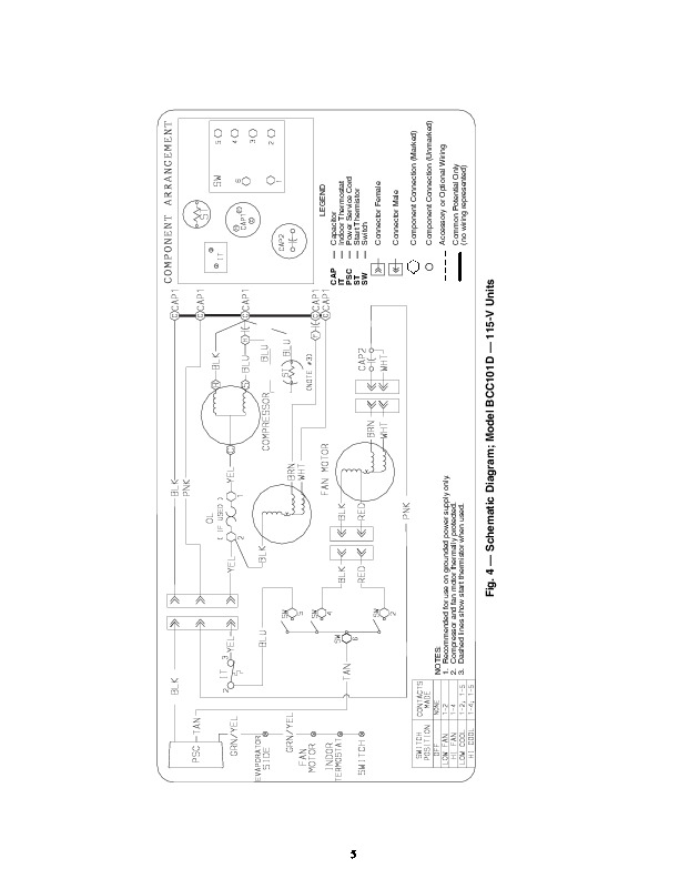
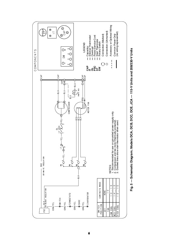
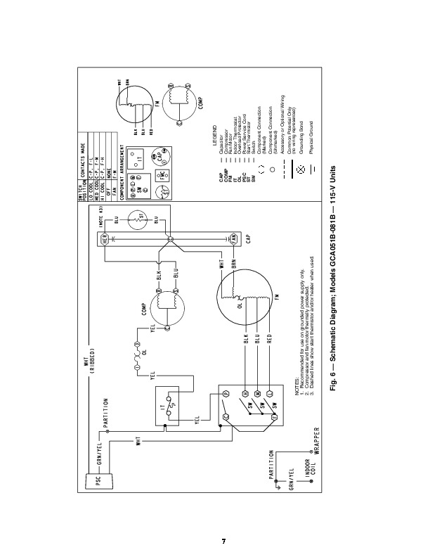
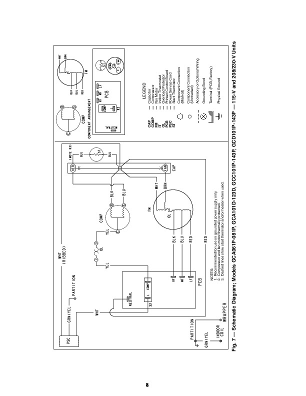
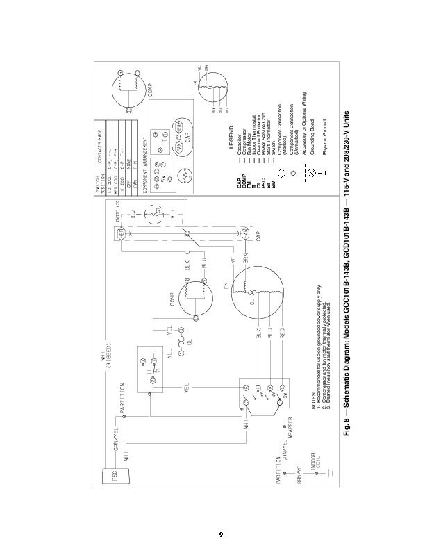
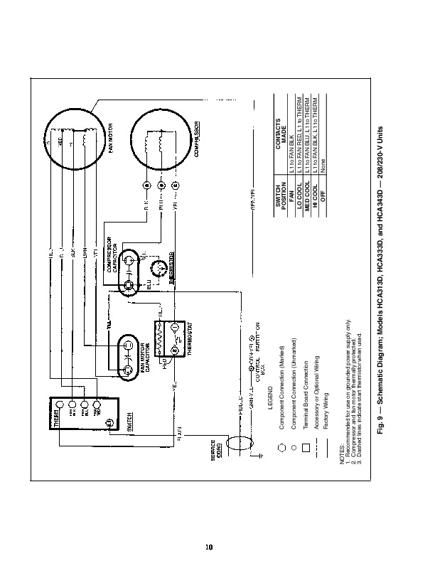
73BC,DC,GC,HC,JC,LC 73RC,TC,UC Series Room Air Conditioners 1998-2003 Wiring Diagrams 73 SERIES ROOM AIR CONDITIONERS INDEX MODEL NO. 73 BCA061X BCA081X, BCA101R BCA101D BCC101D DCA121D, DCA131G, DCA141D, DCB121D, DCB141D, DCC141D DCA153D, DCA183D Common diagram for both 115-v and 208/230-v units.
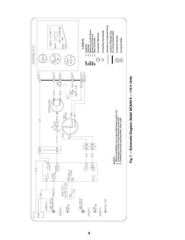
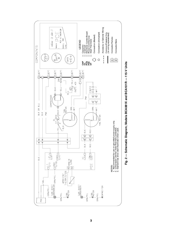
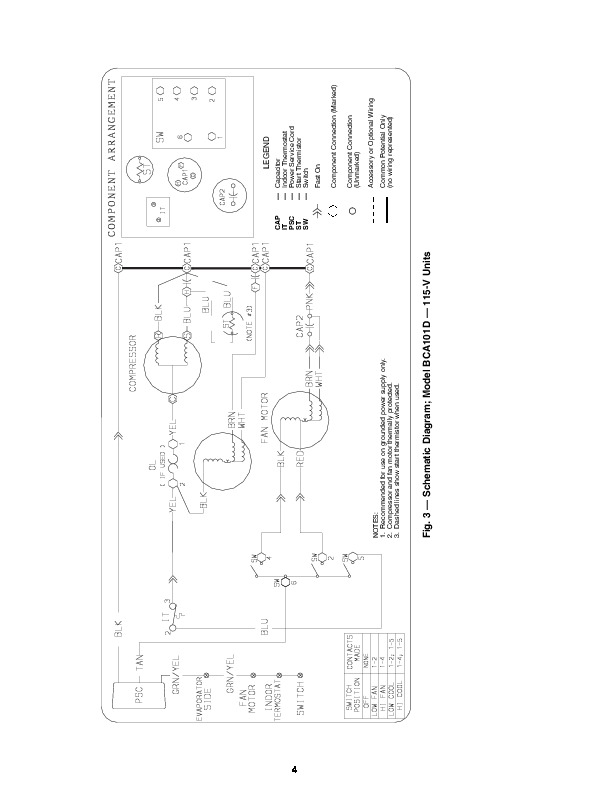
VOLTAGE (1 Ph-60 Hz) 115 115 115 115 115 208/230 115 115 208/230 115 208/230 208/230 208/230 115 LABEL DIAGRAM NO. (SCHEMATIC DESIGNATOR) 11708034 (F) 11708034 (D) 11708034 (A) 11708034 (B) 11708081 (A)* 11708081 (A)* 73GC502684 73GC503264* 73GC503264* 73GC500844* 73GC500844* 51HK501744 11708081 (A)* 73LC500334 11708034 (E) 11708034 (C) 51TH500404 73TC500284 73TC500554 73TC500454 73TC502724 11708100 (A) FIGURE NO. Manufacturer reserves the right to discontinue, or change at any time, specifications or designs without notice and without incurring obligations. PC 131 Catalog No. 537-333 Printed in U.S.A. Form 73-3W Pg 1 3-03 Replaces: New Book 1 4 Tab 8a 10a LEGEND CAP OL PCE PSC ST — — — — — Capacitor Overload Electronic Control Board Power Cord Service Start Thermistor Connection (Marked) Connection (Unmarked) Accessory or Optional Wiring Common Potential Only (no wiring represented) Connector Female Connector Male NOTES: 1. Recommended for use on grounded power supply only. 2. Compressor and fan motor thermally protected. 3. Dashed lines show start thermistor when used. 2 Fig. 1 — Schematic Diagram; Model BCA061X — 115-V Units LEGEND 3 NOTES: 1. Recommended for use on grounded power supply only. 2. Compressor and fan motor thermally protected. 3. Dashed lines show start thermistor when used. CAP OL PCE PSC ST — — — — — Capacitor Overload Electronic Control Board Power Cord Service Start Thermistor Connection (Marked) Connection (Unmarked) Accessory or Optional Wiring Common Potential Only (no wiring represented) Connector Female Connector Male Fig. 2 — Schematic Diagram; Models BCA081X and BCA101R — 115-V Units LEGEND 4 NOTES: 1. Recommended for use on grounded power supply only. 2. Compressor and fan motor thermally protected. 3. Dashed lines show start thermistor when used.