| Categories | Alinco Brand Manuals, Alinco Manuals, Communications Manuals, Consumer Electronic, Two-Way Radio Manuals |
|---|---|
| Tags | Alinco EMS 14 |
| Download File |
|
| Document File Type | |
| Publisher | alinco.com |
| Wikipedia's Page | Alinco |
| Copyright | Attribution Non-commercial |
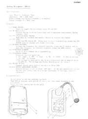
I!lALlHCO Desktop Microphone Specifications: EH-14 type: Electret Condenser Type impedance: 500 – lOOk ohms power consumption: approx 1.5mA(Rx) / 2.5mA(Tx) output voltage: a – 30mV (rms) Controls: ( I) POWER SWITCll, Press to toggle the microphone power On and Off. (2) ON AIR L.E.O., Flashes during stand-by (receiving) and illuminates continuously during transmit (Tx). (3) P1T (Push-To-Talk) SWITCll, Push down to transmit and speak; release to receive and listen.
(4) PTT LOCK, Locks the PTT Switch ON. Press once to start transmitting; press the PTT SWITCII once to release and renume receiving. (5) UP/DOWN SWITCllES, To lune the frequency (or channel) upwards, press the UP switch, and to tune the frequency (or channel) downward, press the OOWN switch. (6) H1CROPIIONE ELEMENT, Speak Lo this element while transmitting. (7) MICROPIIONE CABLE, , Connector pin configuration: J. 1ic Input 2. PTT 3. Down 4. Up 5. +5Vdc* 6. Not to be used · 7. Mic Gnd 8. Ground (*The volli;1ge is supplied by the Alinco transceiver and is used to drive (8) the E IS-14. The voltage may differ depending on the radio.) SWITCll, Changes output audio quality suitable to FM or SSB. (9) fllC OUTPUT AD lUSTMENT VOLUflE, Factory default is set to about lOrnV rms. If the mic sensitivity is too low (or your radio, turn this volume clockwise; if too high. counterclockwise. F I/SSIl Recommendations: – 00 lIot press or hit the switches too hard. – High SWR on antenna. poor ground o( radio. etc. may cause feedback to the microphone. Treat the cable gently and do not pull. 0:, ® «> · · @ @ , 8 Q) (j)
