
| Categories | Carrier HVAC Manuals, HVAC Heating Ventilating Air Conditioning Manuals |
|---|---|
| Tags | Carrier 24ABS3 |
| Download File |
|
| Language | English |
| Product Brand | Support Phone Number: In North America, please call 1-800-CARRIER for immediate customer assistance from 8:00a -5:00p (EST) weekdays, Heating, Ventilating and Air Conditioning - HVAC |
| Document File Type | |
| Publisher | corp.carrier.com |
| Wikipedia's Page | Carrier Corporation |
| Copyright | Attribution Non-commercial |
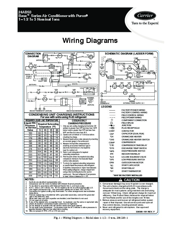
24ABS3 Baset Series Air Conditioner with Puronr 1 1/2 To 5 Nominal Tons Wiring Diagrams CONNECTION DIAGRAM (NOTE #8) *CHS BLK or RED RED or BLK L1 208/230 1Ø POWER SUPPLY L2 BLK BLU BRN CAP YEL H C BLK *CH BLK (NOTE #9) CONT 11 23 EQUIP GND (NOTE #14) YEL/ BLU *LPS YEL YEL *LLS BLK YEL/ BLU BLK BLK *DTS BLK BLU VIO BLK 21 23 BLK YEL BRN/YEL *CTD *HPS BLU T1 BRN/YEL C R EXTERNAL POWER SUPPLY 24 V (NOTE #3) LOGIC T3 T2 Y G R INDOOR THERMOSTAT R C *LLS IFR YEL F BLU YEL BLU BLK YEL BRN OFM *CH (NOTE #14) CONT *HPS *DTS *LPS LOGIC T1 * CTD T3 T2 C S R 2 1 5 *SR *ST +t SCHEMATIC DIAGRAM (LADDER FORM) L1 COMP EQUIP GND *CHS CONT 11 21 COMP R C L2 *SC 5 2 1 S *SC H OFM C F *ST +t CONT 23 23 CAP *SR EXTERNAL POWER SUPPLY 24 V LEGEND FACTORY POWER WIRING FACTORY CONTROL WIRING FIELD CONTROL WIRING FIELD POWER WIRING COMPONENT CONNECTION FIELD SPLICE JUNCTION PLUG RECEPTACLE CONTACTOR CAPACITOR (DUAL RUN) CRANKCASE HEATER CRANKCASE HEATER SWITCH COMPRESSOR COMPRESSOR TIME DELAY DISCHARGE TEMP SWITCH HIGH PRESSURE SWITCH INDOOR FAN RELAY LIQ LINE SOLENOID VALVE LOW PRESSURE SWITCH OUTDOOR FAN MOTOR START CAPICATOR START RELAY START THERMISTOR Y R G INDOOR THERMOSTAT (NOTE #6) INDOOR BLOWER MOTOR CONDENSING UNIT CHARGING INSTRUCTIONS For use with units using R-22 refrigerant REQUIRED LIQUID LINE TEMPERATURE COOLING ONLY Liquid (PSIG) Required Subcooling CHARGING PROCEDURE Pressure 1.
Heating, Ventilating and Air Conditioning User Manual Free Download. HAVC Operator’s Manual. Auto AC Free Instruction Manual Download PDF.
Only use sub cooling charging method when OD at Service Temperature (ºF) ambient is greater than 70ºF and less than 100ºF, Valve indoor temp is greater than 70ºF and less than 5 10 15 20 163 171 179 187 196 205 214 223 7. To obtain the required subcooling temperature at specific liquid line pressure, add refrigerant if liquid line temperature is higher than indicated. When adding refrigerant, charge in liquid form using a flow restricting device into suction service port. Recover refrigerant if temperature is lower. Allow a tolerance of +/- 3ºF. CONT CAP *CH *CHS COMP *CTD *DTS *HPS IFR *LLS *LPS OFM *SC *SR *ST * MAY BE FACTORY INSTALLED NOTES.