| Categories | Carrier HVAC Manuals, HVAC Heating Ventilating Air Conditioning Manuals |
|---|---|
| Tags | Carrier 25HBR |
| Download File |
|
| Language | English |
| Product Brand | Support Phone Number: In North America, please call 1-800-CARRIER for immediate customer assistance from 8:00a -5:00p (EST) weekdays, Heating, Ventilating and Air Conditioning - HVAC |
| Document File Type | |
| Publisher | corp.carrier.com |
| Wikipedia's Page | Carrier Corporation |
| Copyright | Attribution Non-commercial |
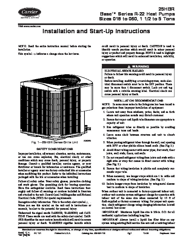
25HBR BaseTM Series R-22 Heat Pumps Sizes 018 to 060, 1 1/2 to 5 Tons Visit www.carrier.com Installation and Start-Up Instructions could result in personal injury or death. CAUTION is used to identify unsafe practices which would result in minor personal injury or product and property damage. NOTE is used to highlight suggestions which will result in enhanced installation, reliability, or operation.
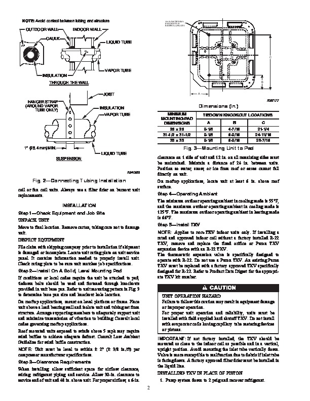
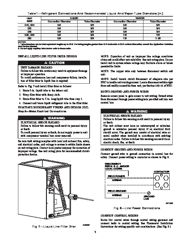
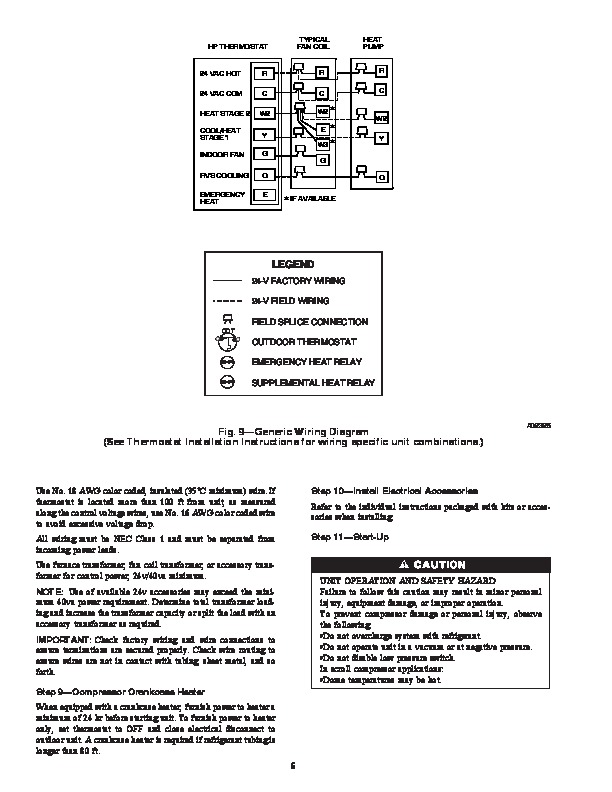
NOTE: Read the entire instruction manual before starting the installation. This symbol indicates a change since the last issue. ELECTRICAL SHOCK HAZARD Failure to follow this warning could result in personal injury or death. Before installing, modifying, or servicing system, main electrical disconnect switch must be in the OFF position. There may be more than 1 disconnect switch. Lock out and tag switch with a suitable warning label. Electrical shock can cause personal injury or death. INSTALLATION RECOMMENDATIONS NOTE: In some cases noise in the living area has been traced to gas pulsations from improper installation of equipment. 1. Locate unit away from windows, patios, decks, and so forth where unit operation sounds may disturb customer. 2. Ensure that vapor- and liquid-tube diameters are appropriate to capacity of unit. 3. Run refrigerant tubes as directly as possible by avoiding unnecessary turns and bends. 4. Leave some slack between structure and unit to absorb vibration. 5. When passing refrigerant tubes through the wall, seal opening with RTV or other pliable silicon based caulk. (See Fig. 2.) 6. Avoid direct tubing contact with water pipes, duct work, floor joists, wall studs, floors, and walls. 7. Do not suspend refrigerant tubing from joists and studs with a rigid wire or strap that comes in direct contact with tubing. (See Fig. 2.) 8. Ensure that tubing insulation is pliable and completely surrounds vapor tube. 9. When necessary, use hanger straps which are 1 in. wide and conform to shape of tubing insulation. (See Fig. 2.) 10. Isolate hanger straps from insulation by using metal sleeves bent to conform to shape of insulation. When outdoor unit is connected to factory-approved indoor unit, outdoor unit contains system refrigerant charge for operation with indoor unit of the same size when connected by 15 ft of field-supplied or factory-accessory tubing. For proper unit operation, check refrigerant charge using charging information located on control box cover. IMPORTANT: Maximum liquid line size is 3/8-in. O.D. for all residential applications including long line. IMPORTANT: Always install a liquid line filter drier on any system using existing field service line sets and or existing indoor Fig. 1–25HBR Dense Grille Unit SAFETY CONSIDERATIONS A05340 Improper installation, adjustment, alteration, service, maintenance, or use can cause explosion, fire, electrical shock, or other conditions which may cause death, personal injury, or property damage. Consult a qualified installer, service agency, or your distributor or branch for information or assistance. The qualified installer or agency must use factory-authorized kits or accessories when modifying this product.