| Categories | Carrier HVAC Manuals, HVAC Heating Ventilating Air Conditioning Manuals |
|---|---|
| Tags | Carrier 58D, Carrier 58P, Carrier 58R, Carrier 58S |
| Download File |
|
| Language | English |
| Product Brand | Support Phone Number: In North America, please call 1-800-CARRIER for immediate customer assistance from 8:00a -5:00p (EST) weekdays, Heating, Ventilating and Air Conditioning - HVAC |
| Document File Type | |
| Publisher | corp.carrier.com |
| Wikipedia's Page | Carrier Corporation |
| Copyright | Attribution Non-commercial |
Inducer Motor Mount Replacement Kit Cancels: New IIK 373L-35-11 8/1/91 Installation Instructions Part No. 318858-751 NOTE: Read the entire instruction before starting the installation. INTRODUCTION This instruction covers the installation of the Inducer Motor Mount Replacement Kit in Models 373LAV, 376CAV, 58DHC, and 58RAV Downflow/Horizontal or Models 383KAV, 395CAV, 58PAV, and 58SSC Upflow Gas Furnaces.
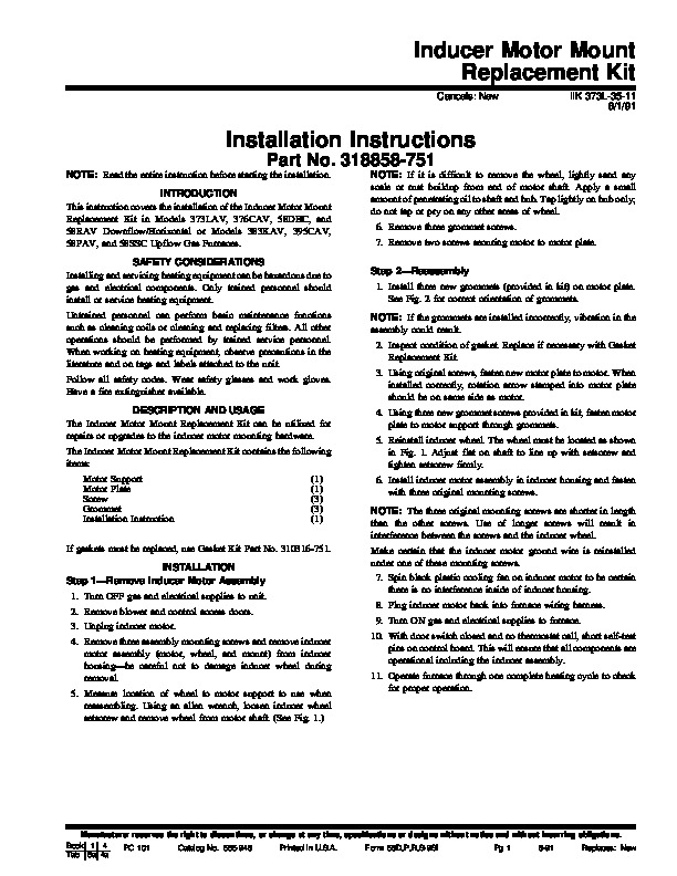
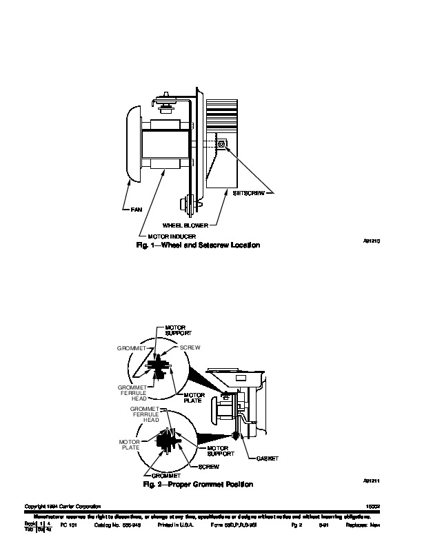
SAFETY CONSIDERATIONS Installing and servicing heating equipment can be hazardous due to gas and electrical components. Only trained personnel should install or service heating equipment. Untrained personnel can perform basic maintenance functions such as cleaning coils or cleaning and replacing filters. All other operations should be performed by trained service personnel. When working on heating equipment, observe precautions in the literature and on tags and labels attached to the unit. Follow all safety codes. Wear safety glasses and work gloves. Have a fire extinguisher available. DESCRIPTION AND USAGE The Inducer Motor Mount Replacement Kit can be utilized for repairs or upgrades to the inducer motor mounting hardware. The Inducer Motor Mount Replacement Kit contains the following items: Motor Support Motor Plate Screw Grommet Installation Instruction (1) (1) (3) (3) (1) NOTE: If it is difficult to remove the wheel, lightly sand any scale or rust buildup from end of motor shaft. Apply a small amount of penetrating oil to shaft and hub. Tap lightly on hub only; do not tap or pry on any other areas of wheel. 6. Remove three grommet screws. 7. Remove two screws securing motor to motor plate. Step 2–Reassembly 1. Install three new grommets (provided in kit) on motor plate. See Fig. 2 for correct orientation of grommets. NOTE: If the grommets are installed incorrectly, vibration in the assembly could result. 2. Inspect condition of gasket. Replace if necessary with Gasket Replacement Kit. 3. Using original screws, fasten new motor plate to motor. When installed correctly, rotation arrow stamped into motor plate should be on same side as motor. 4. Using three new grommet screws provided in kit, fasten motor plate to motor support through grommets. 5. Reinstall inducer wheel. The wheel must be located as shown in Fig. 1. Adjust flat on shaft to line up with setscrew and tighten setscrew firmly. 6. Install inducer motor assembly in inducer housing and fasten with three original mounting screws. NOTE: The three original mounting screws are shorter in length than the other screws. Use of longer screws will result in interference between the screws and the inducer wheel. Make certain that the inducer motor ground wire is reinstalled under one of these mounting screws.