| Categories | Carrier HVAC Manuals, HVAC Heating Ventilating Air Conditioning Manuals |
|---|---|
| Tags | Carrier 58DFA |
| Download File |
|
| Language | English |
| Product Brand | Support Phone Number: In North America, please call 1-800-CARRIER for immediate customer assistance from 8:00a -5:00p (EST) weekdays, Heating, Ventilating and Air Conditioning - HVAC |
| Document File Type | |
| Publisher | corp.carrier.com |
| Wikipedia's Page | Carrier Corporation |
| Copyright | Attribution Non-commercial |
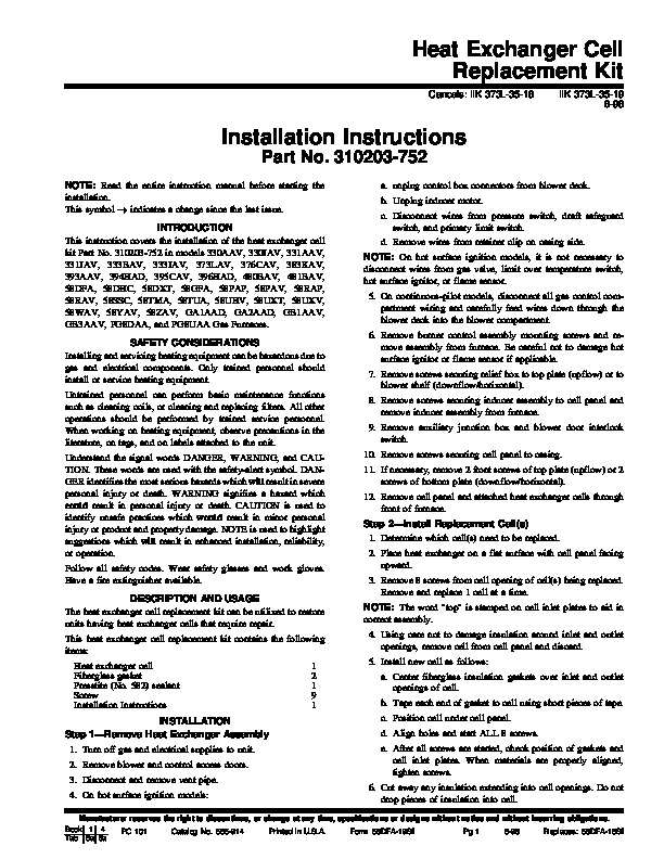
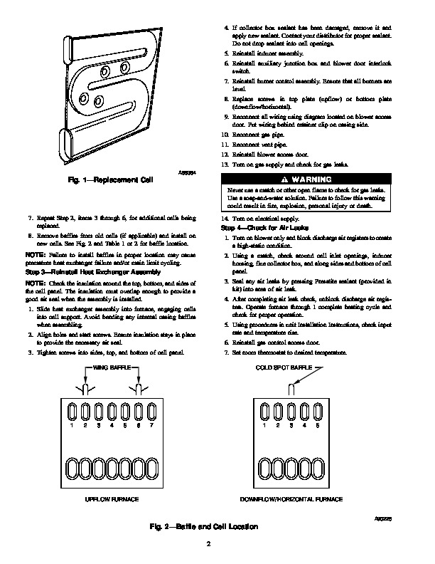
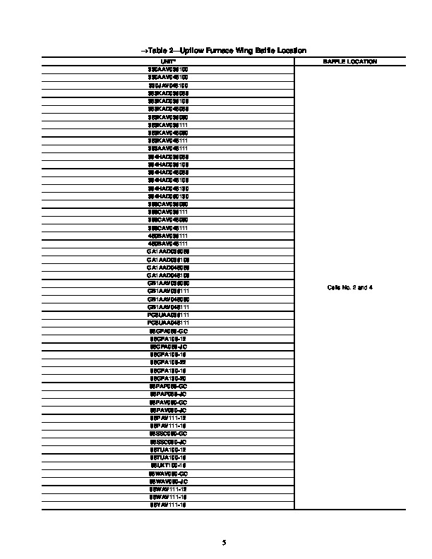
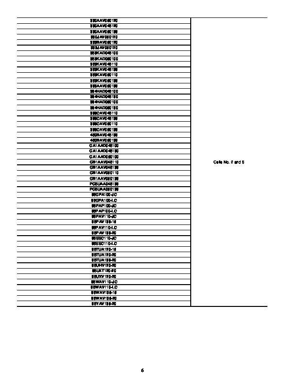
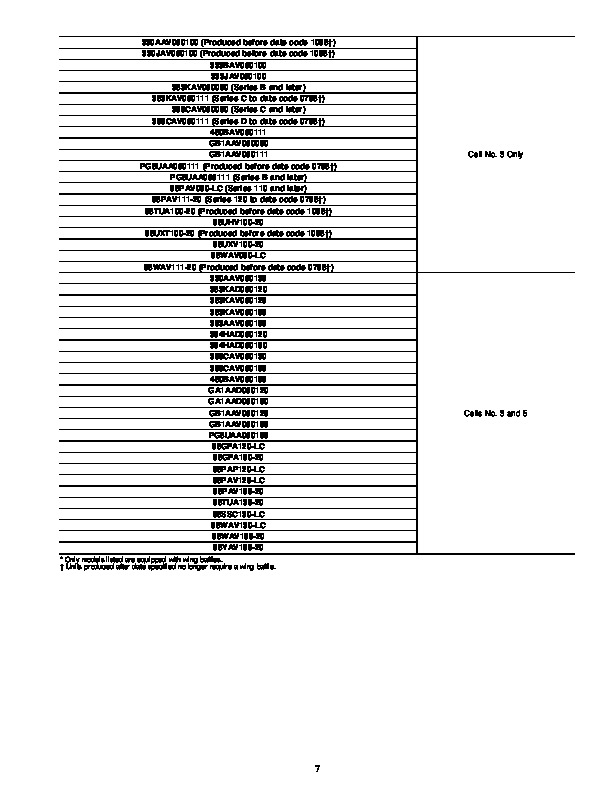
Heat Exchanger Cell Replacement Kit Cancels: IIK 373L-35-18 IIK 373L-35-19 6-98 Installation Instructions Part No. 310203-752 NOTE: Read the entire instruction manual before starting the installation. This symbol indicates a change since the last issue. INTRODUCTION This instruction covers the installation of the heat exchanger cell kit Part No. 310203-752 in models 330AAV, 330JAV, 331AAV, 331JAV, 333BAV, 333JAV, 373LAV, 376CAV, 383KAV, 393AAV, 394HAD, 395CAV, 396HAD, 480BAV, 481BAV, 58DFA, 58DHC, 58DXT, 58GFA, 58PAP, 58PAV, 58RAP, 58RAV, 58SSC, 58TMA, 58TUA, 58UHV, 58UXT, 58UXV, 58WAV, 58YAV, 58ZAV, GA1AAD, GA2AAD, GB1AAV, GB3AAV, PG8DAA, and PG8UAA Gas Furnaces.
Heating, Ventilating and Air Conditioning User Manual Free Download. HAVC Operator’s Manual. Gas Furnace and AC Free Instruction Manual Download PDF.
SAFETY CONSIDERATIONS Installing and servicing heating equipment can be hazardous due to gas and electrical components. Only trained personnel should install or service heating equipment. Untrained personnel can perform basic maintenance functions such as cleaning coils, or cleaning and replacing filters. All other operations should be performed by trained service personnel. When working on heating equipment, observe precautions in the literature, on tags, and on labels attached to the unit. Understand the signal words DANGER, WARNING, and CAUTION. These words are used with the safety-alert symbol. DANGER identifies the most serious hazards which will result in severe personal injury or death. WARNING signifies a hazard which could result in personal injury or death. CAUTION is used to identify unsafe practices which would result in minor personal injury or product and property damage. NOTE is used to highlight suggestions which will result in enhanced installation, reliability, or operation. Follow all safety codes. Wear safety glasses and work gloves. Have a fire extinguisher available. DESCRIPTION AND USAGE The heat exchanger cell replacement kit can be utilized to restore units having heat exchanger cells that require repair. This heat exchanger cell replacement kit contains the following items: Heat exchanger cell Fiberglass gasket Presstite (No. 582) sealant Screw Installation Instructions INSTALLATION Step 1–Remove Heat Exchanger Assembly 1. Turn off gas and electrical supplies to unit. 2. Remove blower and control access doors. 3. Disconnect and remove vent pipe. 4. On hot surface ignition models: 1 2 1 9 1 a. unplug control box connectors from blower deck. b. Unplug inducer motor. c. Disconnect wires from pressure switch, draft safeguard switch, and primary limit switch. d. Remove wires from retainer clip on casing side. NOTE: On hot surface ignition models, it is not necessary to disconnect wires from gas valve, limit over temperature switch, hot surface ignitor, or flame sensor. 5. On continuous-pilot models, disconnect all gas control compartment wiring and carefully feed wires down through the blower deck into the blower compartment. 6. Remove burner control assembly mounting screws and remove assembly from furnace. Be careful not to damage hot surface ignitor or flame sensor if applicable. 7. Remove screws securing relief box to top plate (upflow) or to blower shelf (downflow/horizontal). 8. Remove screws securing inducer assembly to cell panel and remove inducer assembly from furnace. 9. Remove auxiliary junction box and blower door interlock switch. 10. Remove screws securing cell panel to casing. 11. If necessary, remove 2 front screws of top plate (upflow) or 2 screws of bottom plate (downflow/horizontal). 12. Remove cell panel and attached heat exchanger cells through front of furnace. Step 2–Install Replacement Cell(s).