


| Categories | Carrier HVAC Manuals, HVAC Heating Ventilating Air Conditioning Manuals |
|---|---|
| Tags | Carrier 58M |
| Download File |
|
| Language | English |
| Product Brand | Support Phone Number: In North America, please call 1-800-CARRIER for immediate customer assistance from 8:00a -5:00p (EST) weekdays, Heating, Ventilating and Air Conditioning - HVAC |
| Document File Type | |
| Publisher | corp.carrier.com |
| Wikipedia's Page | Carrier Corporation |
| Copyright | Attribution Non-commercial |
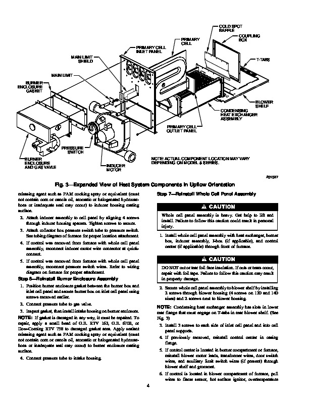
Primary Cell Inlet Panel Kit Cancels: IIK 340M-40-60 IIK 340M-40-71 4-01 Installation Instructions Part No. 320720-751, -753, -754, -755, -756, -757,-758, and -760 NOTE: Read the entire instruction manual before starting the installation. This symbol indicates a change since the last issue. SAFETY CONSIDERATIONS Installation and servicing of heating equipment can be hazardous due to gas and electrical components.
Only trained personnel should install or service heating equipment. Untrained personnel can perform basic maintenance functions such as cleaning and replacing filters. All other operations should be performed by trained service personnel. When working on heating equipment, observe precautions in the literature, on tags, and on labels attached to the unit. Follow all safety codes. Wear safety glasses and work gloves. Have a fire extinguisher available. Recognize safety information. This is the safety-alert symbol. When you see this symbol on the furnace and in instructions or manuals, be alert to the potential for personal injury. Understand the signal words DANGER, WARNING, and CAUTION. These words are used with the safety-alert symbol. DANGER identifies the most serious hazards which will result in severe personal injury or death. WARNING signifies a hazard which could result in personal injury or death. CAUTION is used to identify unsafe practices which would result in minor personal injury or product and property damage. NOTE is used to highlight suggestions which will result in enhanced installation, reliability, or operation. starting installation. DO NOT substitute any other type of RTV sealant. G.E. 162 (P771-9003) is available through RCD in 3-oz tubes. DESCRIPTION AND USAGE Use this primary cell inlet panel kit when replacement of a factory-installed primary cell inlet panel is required. This primary cell inlet panel kit contains the following items: Primary cell inlet panel Burner box gasket Cell mounting screw (No. 8D X 3/8-in.) Installation Instructions INSTALLATION Step 1–Remove Whole Cell Panel Assembly See Fig. 1 and Fig. 2 for furnace component locations. See Fig. 3 for expanded view of heating system components. NOTE: Actual component locations may vary depending on model and series. 1. Turn off gas and electrical supplies to furnace. 2. Remove main furnace door. 3. Remove blower access panel. 4. Disconnect field power supply wires from J-box. 5. Remove 2 screws securing J-box. 6. Remove 2 screws securing top filler panel and rotate panel upwards to remove or allow the heat exchanger to be removed from front of furnace. 7. Disconnect combustion-air intake pipe from intake housing and move pipe out of furnace casing. 8. Disconnect gas supply pipe from gas valve using backup wrench. 9. Disconnect vent pipe from inducer housing by loosening coupling clamp on inducer outlet. If coupling has 2 clamps, loosen clamp on vent pipe side. Move pipe out of furnace casing 10. If control center is located in burner compartment of furnace, remove blower motor leads, transformer wires, door switch wires, and auxiliary limit switch wires (if present) from control center and pull wires through blower shelf.