| Categories | Carrier HVAC Manuals, HVAC Heating Ventilating Air Conditioning Manuals |
|---|---|
| Tags | Carrier 58MTA |
| Download File |
|
| Language | English |
| Product Brand | Support Phone Number: In North America, please call 1-800-CARRIER for immediate customer assistance from 8:00a -5:00p (EST) weekdays, Heating, Ventilating and Air Conditioning - HVAC |
| Document File Type | |
| Publisher | corp.carrier.com |
| Wikipedia's Page | Carrier Corporation |
| Copyright | Attribution Non-commercial |
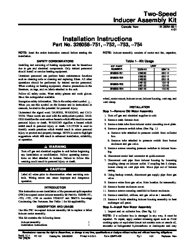
Two-Speed Inducer Assembly Kit Cancels: New IIK 352M-60-1 4-01 Installation Instructions Part No. 326058751, 752, 753, 754 NOTE: Read the entire instruction manual before starting the installation. SAFETY CONSIDERATIONS Installing and servicing of heating equipment can be hazardous due to gas and electrical components. Only trained personnel should install or service heating equipment. Untrained personnel can perform basic maintenance functions such as cleaning coils or cleaning and replacing filters.
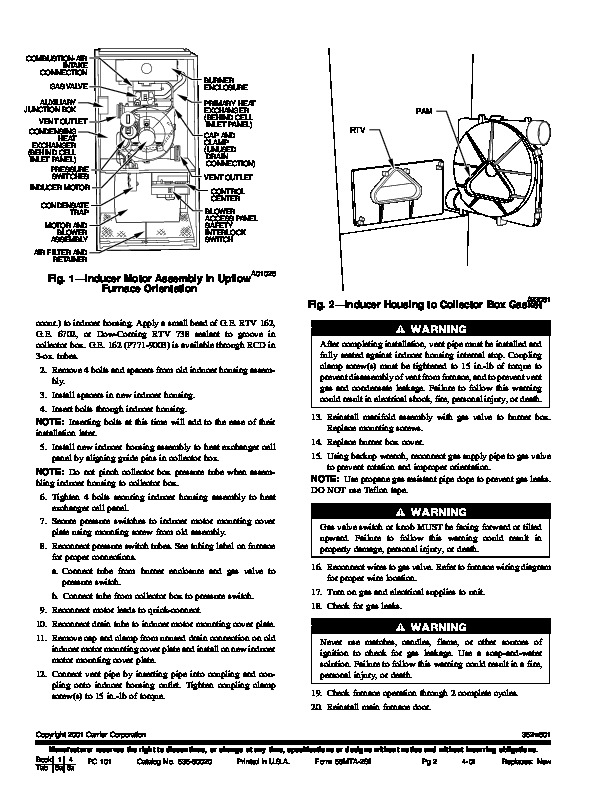
All other operations should be performed by trained service personnel. When working on heating equipment, observe precautions in the literature, on tags, and on labels attached to the unit. Follow all safety codes. Wear safety glasses and work gloves. Have fire extinguisher available Recognize safety information. This is the safety-alert symbol When you see this symbol on the furnace and in instructions or manuals, be alert to the potential for personal injury. Understand the signal word DANGER, WARNING, and CAUTION. These words are used with the safety-alert symbol. DANGER identifies the most serious hazards which will result in severe personal injury or death. WARNING signifies a hazard which could result in personal injury or death. CAUTION is used to identify unsafe practices which would result in minor personal injury or product and property damage. NOTE is used to highlight suggestions which will result in enhanced installation, reliability, or operation. NOTE: Inducer assembly consists of motor and fan, capacitor, Table 1–Kit Usage KIT PART NUMBER 326058-751 326058-752 326058-753 326058-754 UNIT 352MAV 036060 036080 048080 048100 060100 060120 58MTA 060-12 080-12 080-16 100-16 100-20 120-20 wheel, motor mount, inducer cover, inducer housing, vent cap, and vent clamp. INSTALLATION Step 1–Remove Old Motor Assembly 1. Turn off gas and electrical supplies to unit. 2. Remove main furnace door. 3. Remove drain tube from inducer motor mounting cover plate. 4. Remove pressure switch tubes. (See Fig. 1.) a. Remove tube attached to pressure switch from collector box. b. Remove tube attached to pressure switch from burner enclosure and gas valve. 5. Remove screws securing pressure switches to inducer housing. 6. Disconnect motor lead connector at quick-connect. 7. Disconnect vent pipe from inducer housing by loosening coupling clamp on inducer outlet. If coupling has 2 clamps, loosen clamp on vent pipe side. Move pipe out of furnace casing. 8. Using backup wrench, disconnect gas supply pipe from gas valve. 9. Remove wires from gas valve. Note location for reassembly. 10. Remove burner enclosure cover. 11. Remove screws securing manifold to burner enclosure. 12. Remove manifold, orifices, and gas valve as 1 assembly. 13. Remove 4 bolts attaching inducer housing assembly to heat exchanger cell panel. Step 2–Install New Motor Assembly 1. Inspect seal on collector box. (See Fig. 2.) NOTE: If a collector box is damaged in any way, it must be repaired. To repair, apply sealant releasing agent such as PAM cooking spray or equivalent (must not contain corn or canola oil, aromatic or halogenated hydrocarbons or inadequate seal may Turn off gas and electrical supplies to unit before beginning any installation or modification. Follow operating instructions on label attached to furnace. Failure to follow this warning could result in personal injury or death. Label all wires prior to disconnection when servicing controls. Wiring errors can cause improper and dangerous operation. INTRODUCTION This instruction covers installation of the permanent split capacitor (PSC) two-speed motor inducer assembly kit Part No. 326058-751, -752, -753, -754 on models 352MAV and 58MTA two-stage Condensing Gas Furnaces. See Table 1 for kit applicability. DESCRIPTION AND USAGE Use this PSC two-speed inducer assembly kit to replace a failed inducer motor assembly.