
| Categories | Carrier HVAC Manuals, HVAC Heating Ventilating Air Conditioning Manuals |
|---|---|
| Tags | Carrier 58MVP |
| Download File |
|
| Language | English |
| Product Brand | Support Phone Number: In North America, please call 1-800-CARRIER for immediate customer assistance from 8:00a -5:00p (EST) weekdays, Heating, Ventilating and Air Conditioning - HVAC |
| Document File Type | |
| Publisher | corp.carrier.com |
| Wikipedia's Page | Carrier Corporation |
| Copyright | Attribution Non-commercial |
58MVP 4-Way Multipoise Direct-Vent Variable-Capacity Condensing Gas Furnace Visit www.carrier.com Installation, Start-Up, and Operating Instructions For Sizes 040–120, Series 170 NOTE: Read the entire instruction manual before starting the installation. ama CERTIFIED A93040 This symbol indicates a change since the last issue. Index Page DIMENSIONAL DRAWING 3 SAFETY CONSIDERATIONS .2 Clearances to Combustibles 4 CODES AND STANDARDS 5 ELECTROSTATIC DISCHARGE (ESD) PRECAUTIONS 5 INTRODUCTION 5 APPLICATIONS 5 General 5 Upflow Applications .5 Downflow Applications 8 Horizontal Left (Supply-Air Discharge) Applications 9 Horizontal Right (Supply-Air Discharge) Applications 11 LOCATION 13 General 13 Low-Heat Only Installation 14 Furnace Location Relative to Cooling Equipment 14 Hazardous Locations .14 INSTALLATION .15 Leveling Legs (If Desired) .15 Installation In Upflow or Downflow Applications 15 Installation In Horizontal Applications 15 Air Ducts .15 General Requirements .15 Ductwork Acoustical Treatment .17 Supply-Air Connections 17 Return-Air Connections .18 Filter Arrangement 18 Bottom Closure Panel .18 Gas Piping .18 Electrical Connections 20 115-v Wiring 20 24-v Wiring 21 Accessories 22 Direct Venting .22 Removal of Existing Furnaces from Common Vent Systems 22 Combustion-Air and Vent Piping .24 Concentric Vent and Combustion-Air Termination Kit Installation 28 Multiventing and Vent Terminations 31 Condensate Drain 34 As an ENERGY STAR® Partner, Carrier Corporation has determined that this product meets the ENERGY STAR® guidelines for energy efficiency.
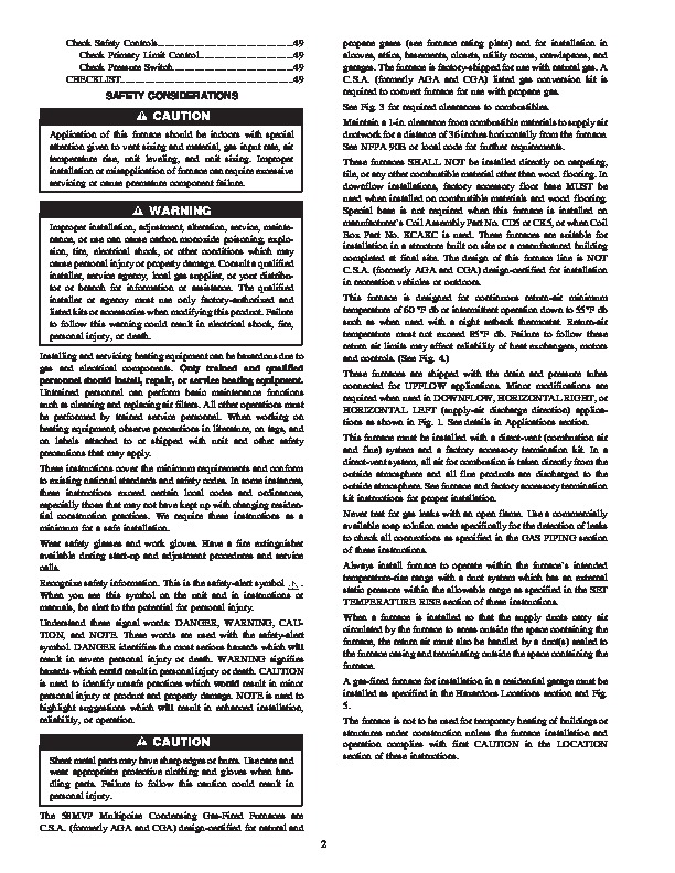
REGISTERED QUALITY SYSTEM AIRFLOW UPFLOW HORIZONTAL LEFT DOWNFLOW AIRFLOW HORIZONTAL RIGHT AIRFLOW AIRFLOW Fig. 1–Multipoise Orientations A93041 General .34 Application .34 Condensate Drain Protection .35 START-UP, ADJUSTMENTS AND SAFETY CHECK 35 General .35 Select Setup Switch Positions .35 Prime Condensate Trap With Water .36 Purge Gas Lines 36 Sequence of Operation 37 Single-Stage Thermostat and Two-Stage Heating (Adaptive Mode) .37 Two-Stage Thermostat and Two-Stage Heating .39 Cooling Mode .39 Thermidistat Mode .40 Super-Dehumidify Mode 40 Continuous Blower Mode 40 Heat Pump 40 Component Test .41 Adjustments .41 Set Gas Input Rate .41 Set Temperature Rise .48 Set Thermostat Heat Anticipator .48 Manufacturer reserves the right to discontinue, or change at any time, specifications or designs without notice and without incurring obligations. Book 1 4 PC 101 Catalog No. 535-80110 Printed in U.S.A. Form 58MVP-13SI Pg 1 1-04 Replaces: 58MVP-12SI Tab 6a 8a Check Safety Controls .49 Check Primary Limit Control 49 Check Pressure Switch .49 CHECKLIST 49 SAFETY CONSIDERATIONS propane gases (see furnace rating plate) and for installation in alcoves, attics, basements, closets, utility rooms, crawlspaces, and garages. The furnace is factory-shipped for use with natural gas. A C.S.A. (formerly AGA and CGA) listed gas conversion kit is required to convert furnace for use with propane gas. See Fig. 3 for required clearances to combustibles. Maintain a 1-in. clearance from combustible materials to supply air ductwork for a distance of 36 inches horizontally from the furnace. See NFPA 90B or local code for further requirements. These furnaces SHALL NOT be installed directly on carpeting, tile, or any other combustible material other than wood flooring. In downflow installations, factory accessory floor base MUST be used when installed on combustible materials and wood flooring. Special base is not required when this furnace is installed on manufacturer’s Coil Assembly Part No. CD5 or CK5, or when Coil Box Part No. KCAKC is used. These furnaces are suitable for installation in a structure built on site or a manufactured building completed at final site. The design of this furnace line is NOT C.S.A. (formerly AGA and CGA) design-certified for installation in recreation vehicles or outdoors. This furnace is designed for continuous return-air minimum temperature of 60 °F db or intermittent operation down to 55°F db such as when used with a night setback thermostat.