

| Categories | Carrier HVAC Manuals, HVAC Heating Ventilating Air Conditioning Manuals |
|---|---|
| Tags | Carrier 58ST |
| Download File |
|
| Language | English |
| Product Brand | Support Phone Number: In North America, please call 1-800-CARRIER for immediate customer assistance from 8:00a -5:00p (EST) weekdays, Heating, Ventilating and Air Conditioning - HVAC |
| Document File Type | |
| Publisher | corp.carrier.com |
| Wikipedia's Page | Carrier Corporation |
| Copyright | Attribution Non-commercial |
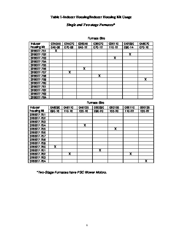
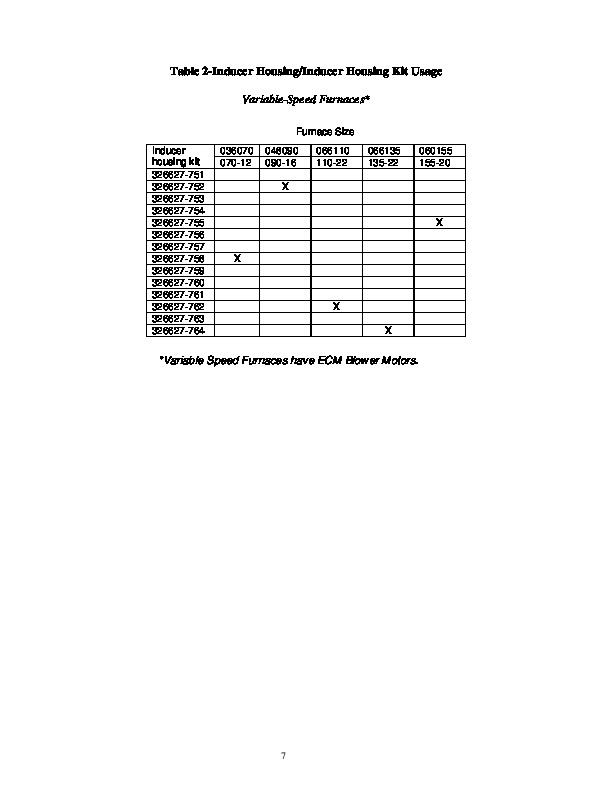
Replacement Inducer Housing Kit Cancels: New IIK-310-45-4 6-02 Installation Instructions Part No. 326627-751 thru 326627-755 Note: Read the entire instruction manual before starting the installation. SAFETY CONSIDERATIONS Installing and servicing heating equipment can be hazardous due to gas and electrical components. Only trained personnel should install or service heating equipment. Untrained personnel can perform basic maintenance functions such as cleaning coils, or cleaning and replacing filters.
All other operations should be performed by trained service personnel. When working on heating equipment, observe precautions in the literature, on tags, and on labels attached to the unit. Recognize safety information. This is the safety-alert symbol. When you see this symbol on the unit and in instructions or manuals, be alert to the potential for personal injury. Understand the signal words DANGER, WARNING, and CAUTION. These words are used with the safety-alert symbol. DANGER identifies the most serious hazards which will result in severe personal injury or death. WARNING signifies a hazard which could result in personal injury or death. CAUTION is used to identify unsafe practices which would result in minor personal injury or product and property damage. NOTE is used to highlight suggestions which will result in enhanced installation, reliability, or operation. Follow all safety codes. Wear safety glasses and work gloves. Have a fire extinguisher available. INTRODUCTION This instruction covers the inducer housing installation on mid-efficiency hot surface ignitor units. The inducer housing should be replaced when corrosion has created visible surface damage to the box, damage to the pressure switch pressure tap or anytime functionality of the inducer housing has been compromised. There are 4 different primary sizes of inducer housings, each having up to 4 different sizes of flue restriction openings. Total there are 13 different combinations of inducer housings. See Tables 1 and 2 at the end of these instructions for a complete listing of kits and applicable models. NOTE: It is very important that you verify that the inducer housing you are installing be the same size as you are removing. Always verify the flue restrictor HOLE SIZE before installing an inducer housing. See Table 1 or 2. DESCRIPTION AND USAGE The inducer housing replacement kit can be utilized to restore units having inducer housings that require repair. This kit contains the following items: Inducer housing, Inducer housing screws, Inducer motor mounting screws, Vent elbow screws, Inducer motor gasket and Installation Instructions. INSTALLATION Note: A releasing agent such as PAM cooking spray or equivalent (must not contain corn or canola oil, aromatic or halogenated hydrocarbons or inadequate seal may occur) and RTV sealant (G.E. 162, G.E. 6702, or Dow-Corning 738) are needed before starting installation. DO NOT substitute any other type of RTV sealant. G.E. 162 (P771-9003) is available through RCD in 3-oz tubes.