| Categories | Carrier HVAC Manuals, HVAC Heating Ventilating Air Conditioning Manuals |
|---|---|
| Tags | Carrier 58ST |
| Download File |
|
| Language | English |
| Product Brand | Support Phone Number: In North America, please call 1-800-CARRIER for immediate customer assistance from 8:00a -5:00p (EST) weekdays, Heating, Ventilating and Air Conditioning - HVAC |
| Document File Type | |
| Publisher | corp.carrier.com |
| Wikipedia's Page | Carrier Corporation |
| Copyright | Attribution Non-commercial |
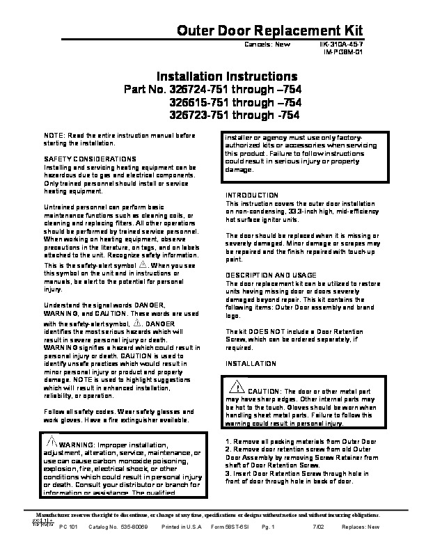
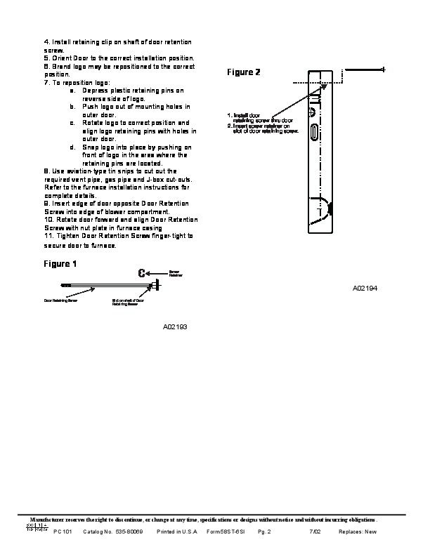
Outer Door Replacement Kit Cancels: New IIK-310A-45-7 IM-PG8M-01 Installation Instructions Part No. 326724-751 through 754 326615-751 through 754 326723-751 through -754 NOTE: Read the entire instruction manual before starting the installation. SAFETY CONSIDERATIONS Installing and servicing heating equipment can be hazardous due to gas and electrical components. Only trained personnel should install or service heating equipment.
Untrained personnel can perform basic maintenance functions such as cleaning coils, or cleaning and replacing filters. All other operations should be performed by trained service personnel. When working on heating equipment, observe precautions in the literature, on tags, and on labels attached to the unit. Recognize safety information When you see This is the safety-alert symbol this symbol on the unit and in instructions or manuals, be alert to the potential for personal injury. Understand the signal words DANGER, WARNING, and CAUTION. These words are used. DANGER with the safety-alert symbol, identifies the most serious hazards which will result in severe personal injury or death. WARNING signifies a hazard which could result in personal injury or death. CAUTION is used to identify unsafe practices which would result in minor personal injury or product and property damage. NOTE is used to highlight suggestions which will result in enhanced installation, reliability, or operation. Follow all safety codes. Wear safety glasses and work gloves. Have a fire extinguisher available. WARNING: Improper installation, adjustment, alteration, service, maintenance, or use can cause carbon monoxide poisoning, explosion, fire, electrical shock, or other conditions which could result in personal injury or death. Consult your distributor or branch for information or assistance. The qualified installer or agency must use only factoryauthorized kits or accessories when servicing this product. Failure to follow instructions could result in serious injury or property damage. INTRODUCTION This instruction covers the outer door installation on non-condensing, 33.3-inch high, mid-efficiency hot surface ignitor units. The door should be replaced when it is missing or severely damaged. Minor damage or scrapes may be repaired and the finish repaired with touch-up paint. DESCRIPTION AND USAGE The door replacement kit can be utilized to restore units having missing door or doors severely damaged beyond repair. This kit contains the following items: Outer Door assembly and brand logo. The kit DOES NOT include a Door Retention Screw, which can be ordered separately, if required. INSTALLATION CAUTION: The door or other metal part may have sharp edges. Other internal parts may be hot to the touch. Gloves should be worn when handling sheet metal parts. Failure to follow this warning could result in personal injury. 1. Remove all packing materials from Outer Door 2. Remove door retention screw from old Outer Door Assembly by removing Screw Retainer from shaft of Door Retention Screw. 3. Insert Door Retention Screw through hole in front of door through hole in back of door. Manufacturer reserves the right to discontinue, or change at any time, specifications or designs without notice and without incurring obligations. PC 101 Catalog No. 535-80069 Printed in U.S.A Form 58ST-6SI Pg. 1 7/02 Replaces: New 4. Install retaining clip on shaft of door retention screw.