

| Categories | Carrier HVAC Manuals, HVAC Heating Ventilating Air Conditioning Manuals |
|---|---|
| Tags | Carrier 58ST |
| Download File |
|
| Language | English |
| Product Brand | Support Phone Number: In North America, please call 1-800-CARRIER for immediate customer assistance from 8:00a -5:00p (EST) weekdays, Heating, Ventilating and Air Conditioning - HVAC |
| Document File Type | |
| Publisher | corp.carrier.com |
| Wikipedia's Page | Carrier Corporation |
| Copyright | Attribution Non-commercial |
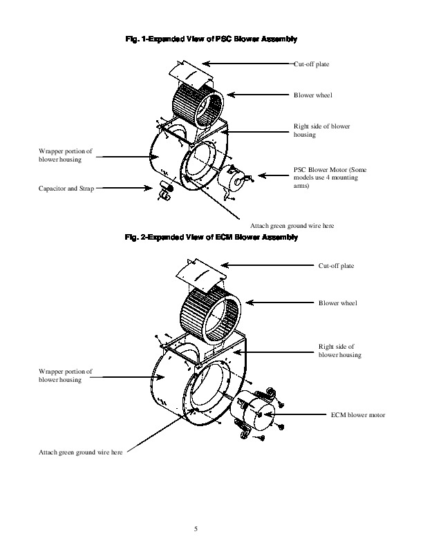
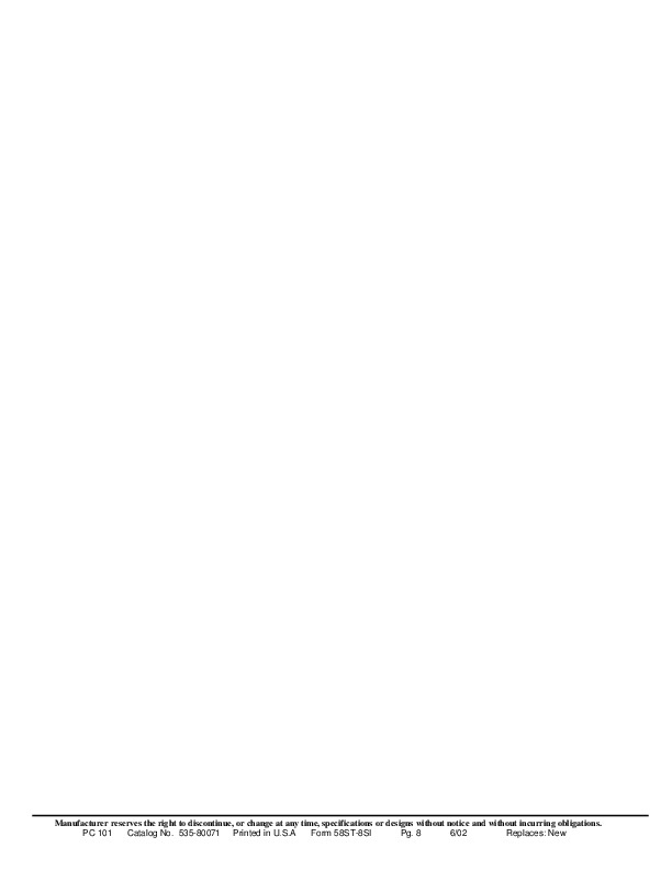
Blower Housing Replacement Kit Cancels: New IIK-310A-45-9 6/02 Installation Instructions Part No. 327265-751 thru 327265-753 Part No. 327266-751 and 327266-753 NOTE: Read the entire instruction manual before starting the installation. SAFETY CONSIDERATIONS Installing and servicing heating equipment can be hazardous due to gas and electrical components. Only trained personnel should install or service heating equipment.
Untrained personnel can perform basic maintenance functions such as cleaning coils, or cleaning and replacing filters. All other operations should be performed by trained service personnel. When working on heating equipment, observe precautions in the literature, on tags, and on labels attached to the unit. Recognize safety information. This is the safety-alert symbol. When you see this symbol on the unit and in instructions or manuals, be alert to the potential for personal injury. Understand the signal words DANGER, WARNING, and CAUTION. These words are used with the safety-alert symbol,. DANGER identifies the most serious hazards which will result in severe personal injury or death. WARNING signifies a hazard which could result in personal injury or death. CAUTION is used to identify unsafe practices which would result in minor personal injury or product and property damage. NOTE is used to highlight suggestions which will result in enhanced installation, reliability, or operation. Follow all safety codes. Wear safety glasses and work gloves. Have a fire extinguisher available. INTRODUCTION This instruction covers the blower housing installation on non-condensing, 33.3 inch high, mid-efficiency hot surface ignitor units. The blower housing should be replaced when there is visible damage to the blower housing. DESCRIPTION AND USAGE The blower housing replacement kit can be utilized to restore units having blower assemblies that require repair. This kit contains the following items: Blower housing assembly with cut-off plate and a loose parts bag with screws. A replacement motor and blower wheel are NOT included in this kit and must be ordered separately. INSTALLATION Step 1–Remove the Existing Blower Assembly 1. Turn off electric supplies to unit and thermostat. More than 1 disconnect may be required to disconnect power to unit. 2. Remove exterior door by loosening knurled knob on door and pulling forward. 3. Turn off gas at external supply shutoff and turn electric switch on gas valve to “OFF “. CAUTION: Vent connector may be hot to the touch or have sharp edges. Gloves should be worn when handling sheet metal parts. Failure to follow this warning could result in personal injury. 4. On downflow or horizontal positions where the vent connector passes in front of the blower access panel, disconnect and remove vent connector from vent elbow. NOTE: Support vent connector with temporary metal strap to prevent damage to vent connector or vent connector elbows. 5. Remove the screws that secure the blower access door and set door aside.