| Categories | HVAC Heating Ventilating Air Conditioning Manuals, Mitsubishi HVAC Manuals |
|---|---|
| Tags | Mitsubishi Mr Slim PEA RP250 WHA |
| Download File |
|
| Language | English |
| Product Brand | Heating, Ventilating and Air Conditioning Manual, Mitsubishi Electric US, Inc. Americas Corporate Office Phone: 714-220-2500; Application support or for technical information regarding applications for Mr. Slim, Toll-free: 1-800-433-4822 |
| Document File Type | |
| Publisher | mehvac.com |
| Wikipedia's Page | Mitsubishi Electric |
| Copyright | Attribution Non-commercial |
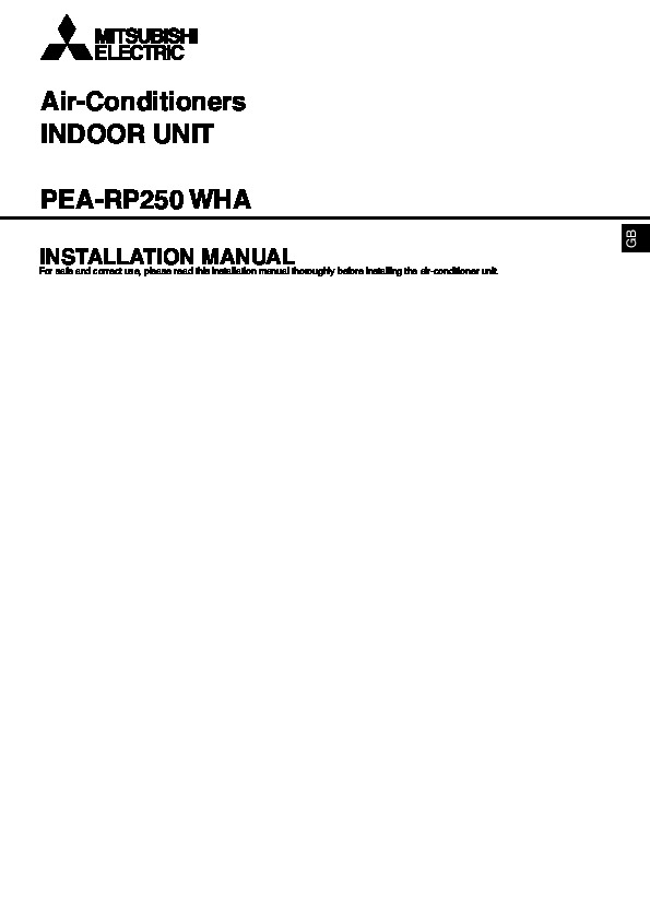
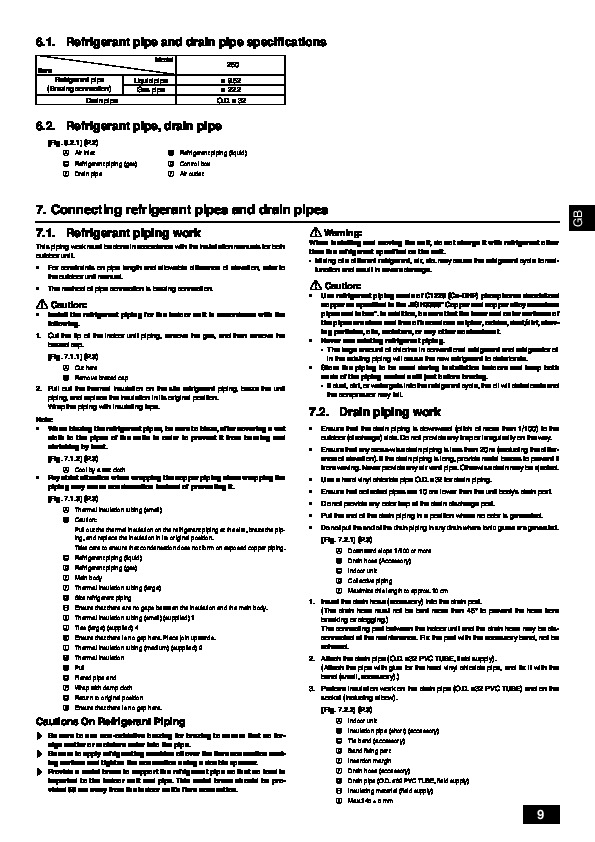
Air-Conditioners INDOOR UNIT PEA-RP250 WHA INSTALLATIONthis installation manual thoroughly before installing the air-conditioner unit. MANUAL For safe and correct use, please read GB 3 [Fig. 3.2.1] 800 150 200 1100 3.2 C 200 300 B 1350 450 1034 A 730 Keep the service space for the maintenance from the bottom when the heat exchanger is cleaned. 50 23 D 50 1100 1250 1324 more than 100 37 23 60 more than 20 470 more than 20 30 ±10 A B C D E Access door Electrical parts box Air inlet Air outlet Ceiling surface E A 4 [Fig.
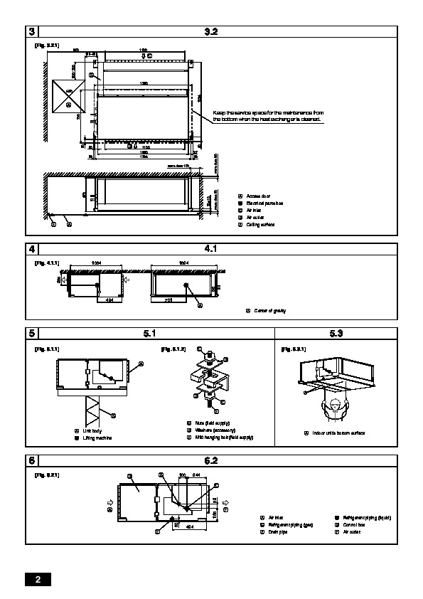
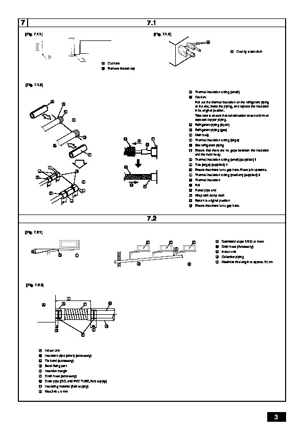
Lifting machine D E A E Nuts (field supply) Washers (accessory) M10 hanging bolt (field supply) A Indoor unit’s bottom surface 6 [Fig. 6.2.1] Air inlet Refrigerant piping (gas) Drain pipe B D F Refrigerant piping (liquid) Control box Air outlet E 424 2 7 [Fig. 7.1.1] 7.1 [Fig. 7.1.2] A A Cool by a wet cloth A B Cut here Remove brazed cap [Fig. 7.1.3] A B Thermal insulation tubing (small) Caution: Pull out the thermal insulation on the refrigerant piping at the site, braze the piping, and replace the insulation in its original position. A B C E C D E Take care to ensure that condensation does not form on exposed copper piping. Refrigerant piping (liquid) Refrigerant piping (gas) Main body Thermal insulation tubing (large) Site refrigerant piping Ensure that there are no gaps between the insulation and the main body. Thermal insulation tubing (small) (supplied) 1 Ties (large) (supplied) 4 Ensure that there is no gap here. Place join upwards. Thermal insulation tubing (medium) (supplied) 2 Thermal insulation Pull Flared pipe end Wrap with damp cloth Return to original position Ensure that there is no gap here. Downward slope 1/100 or more Drain hose (Accessory) Indoor unit Collective piping Maximize this length to approx. 10 cm [Fig. 7.2.2] I A B F G 5 25 D C E H A B C D E F G H I Indoor unit Insulation pipe (short) (accessory) Tie band (accessory) Band fixing part Insertion margin Drain hose (accessory) Drain pipe (O.D. ø32 PVC TUBE, field supply) Insulating material (field supply) Max.145 ± 5 mm 3 8