
| Categories | HVAC Heating Ventilating Air Conditioning Manuals, Mitsubishi HVAC Manuals |
|---|---|
| Tags | Mitsubishi Mr Slim PUHZ RP250YHM A |
| Download File |
|
| Language | English |
| Product Brand | Heating, Ventilating and Air Conditioning Manual, Mitsubishi Electric US, Inc. Americas Corporate Office Phone: 714-220-2500; Application support or for technical information regarding applications for Mr. Slim, Toll-free: 1-800-433-4822 |
| Document File Type | |
| Publisher | mehvac.com |
| Wikipedia's Page | Mitsubishi Electric |
| Copyright | Attribution Non-commercial |
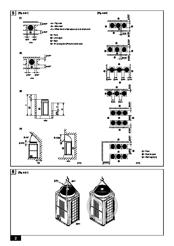
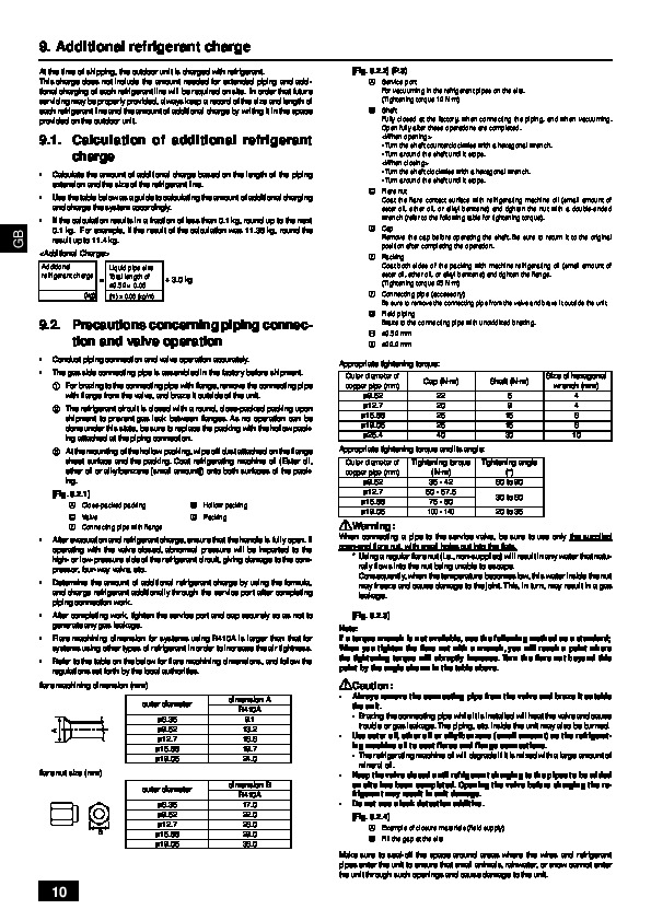
OUTDOOR UNIT PUHZ-RP250YHM-A For use with R410A INSTALLATIONthis installation manual thoroughly before installing the air-conditioner unit. MANUAL For safe and correct use, please read GB (1) 300* : Top view : Side view : When there is little space up to an obstruction C B A C 30 450* 100* 300* 5 [Fig. 5.0.1] [Fig. 5.0.2] B A 450* A : Front B : Unit height C : Back D : Air outlet guide (Procured at the site) 15* 15* C B B A C 100 B (2) 100* A 450* C C 50* 50* 450* 450 450 100* B C (3) h H B 500 H A h C B 900 900 300* 300* B 300* B 450 450 A (4) C 45° 240 1000 D A C C 15* 450* A A : Front B : Must be open C : Wall height (H) 50 (mm) 1000* B (mm) 6 [Fig.
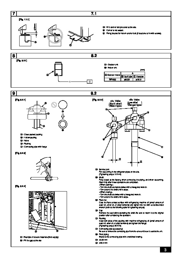
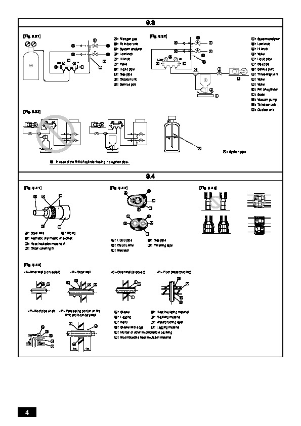
Open fully after these operations are completed. · Turn the shaft counterclockwise with a hexagonal wrench. · Turn around the shaft until it stops. · Turn the shaft clockwise with a hexagonal wrench. · Turn around the shaft until it stops. C: Flare nut Coat the flare contact surface with refrigerating machine oil (small amount of ester oil, ether oil, or alkyl benzene) and tighten the nut with a double-ended wrench (refer to the following table for tightening torque). D: Cap Remove the cap before operating the shaft. Be sure to return it to the original position after completing the operation. E: Packing Coat both sides of the packing with machine refrigerating oil (small amount of ester oil, ether oil, or alkyl benzene) and tighten the flange. (Tightening torque 25 N·m) [Fig. 9.2.4] A B F: Connecting pipe (accessory) Be sure to remove the connecting pipe from the valve and braze it outside the unit. G: Field piping Braze to the connecting pipe with unoxidized brazing. H: ø9.52 mm I: ø22.2 mm A : Example of closure materials (field supply) B : Fill the gap at the site 3 9.3 [Fig. 9.3.1] F B B C A C LOW HI A : Nitrogen gas [Fig. 9.3.2] D N N E F O HI A : System analyzer B : Low knob C : Hi knob D : Valve E : Liquid pipe F : Gas pipe G H I E J B : To indoor unit C : System analyzer D : Low knob E : Hi knob F : Valve G : Liquid pipe H : Gas pipe I : Outdoor unit J : Service port LOW A D B C H G I K J L M G : Service port H : Three-way joint I : Valve J : Valve K : R410A cylinder L : Scale M : Vacuum pump N : To indoor unit O : Outdoor unit [Fig. 9.3.3] A A : Syphon pipe B In case of the R410A cylinder having no syphon pipe. 9.4 [Fig. 9.4.1] B A C [Fig. 9.4.2] A B C E D [Fig. 9.4.3] E E A D D A : Steel wire E B : Piping B C : Asphaltic oily mastic or asphalt D : Heat insulation material A E : Outer covering B A : Liquid pipe C : Electric wire E : Insulator B : Gas pipe D : Finishing tape [Fig. 9.4.4] Inner wall (concealed) Outer wall Outer wall (exposed)