| Categories | HVAC Heating Ventilating Air Conditioning Manuals, Mitsubishi HVAC Manuals |
|---|---|
| Tags | Mitsubishi MS MSH A30, Mitsubishi MSH A24 WV |
| Download File |
|
| Language | English |
| Product Brand | Heating, Ventilating and Air Conditioning Manual, Mitsubishi Electric US, Inc. Americas Corporate Office Phone: 714-220-2500; Application support or for technical information regarding applications for Mr. Slim, Toll-free: 1-800-433-4822 |
| Document File Type | |
| Publisher | mehvac.com |
| Wikipedia's Page | Mitsubishi Electric |
| Copyright | Attribution Non-commercial |
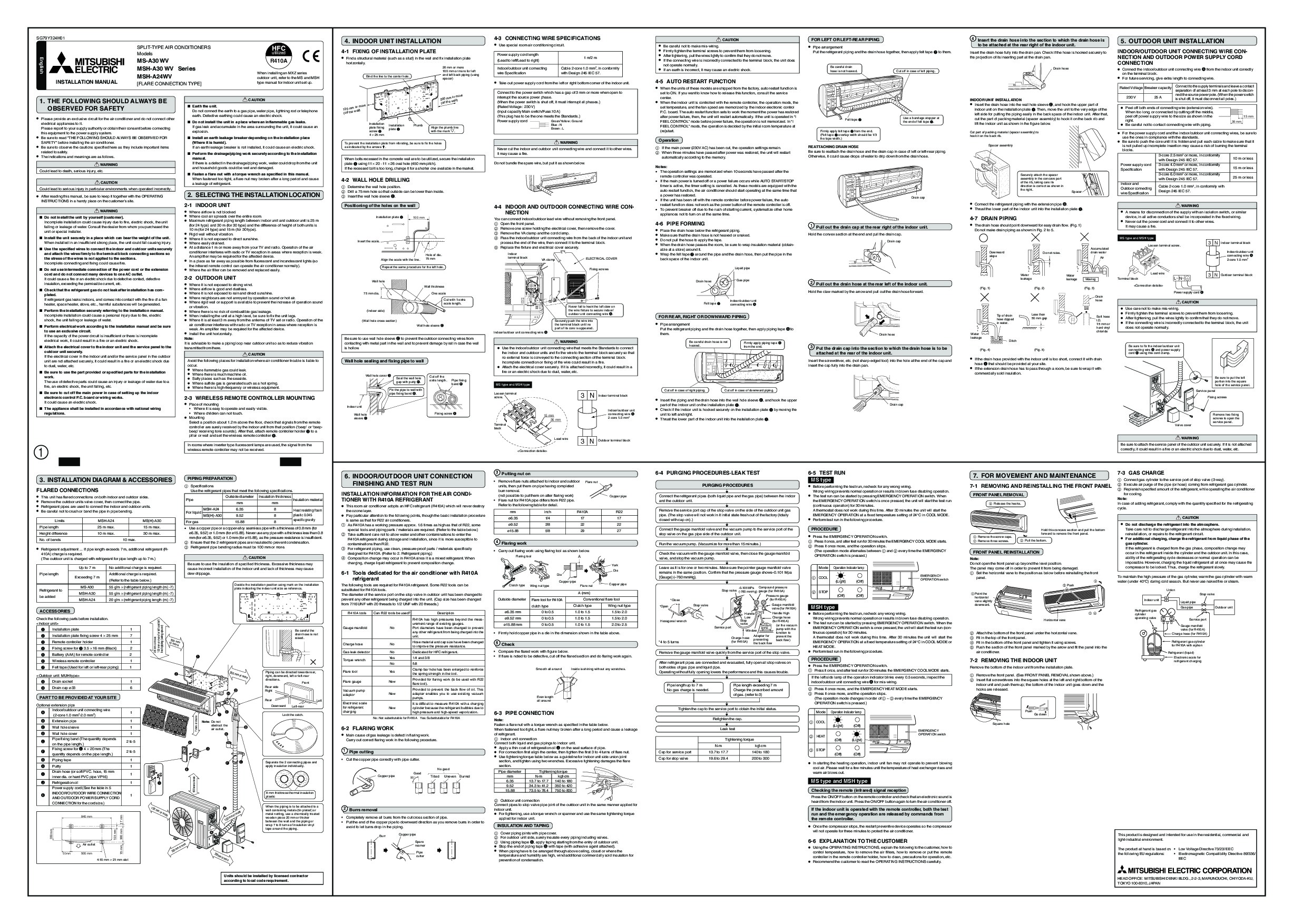
SG79Y324H01 4. INDOOR UNIT INSTALLATION SPLIT-TYPE AIR CONDITIONERS Models utilized 4-3 CONNECTING WIRE SPECIFICATIONS CAUTION FOR LEFT OR LEFT-REAR PIPING HFC · Use special room air conditioning circuit. Power supply cord length (Lead to left/Lead to right) Indoor/outdoor unit connecting wire Specification 4-1 FIXING OF INSTALLATION PLATE MS-A30 WV MSH-A30 WV Series MSH-A24WV INSTALLATION MANUAL [FLARE CONNECTION TYPE] R410A When installing an MXZ series outdoor unit, refer to the MS and MSH type manual for indoor unit set up.
· Find a structural material (such as a stud) in the wall and fix installation plate horizontally. 26 mm or more 100 mm or more for left and left back piping (using spacer) 1 m/2 m Cable 2-core 1.0 mm2, in conformity with Design 245 IEC 57. · Be careful not to make mis-wiring. Firmly tighten the terminal screws to prevent them from loosening. After tightening, pull the wires lightly to confirm that they do not move. If the connecting wire is incorrectly connected to the terminal block, the unit does not operate normally. If an earth is incorrect, it may cause an electric shock. · Pipe arrangement Put the refrigerant piping and the drain hose together, then apply felt tape 7 to them. 4 Insert the drain hose into the section to which the drain hose is to be attached at the rear right of the indoor unit. Insert the drain hose fully into the drain pan. Check if the hose is hooked securely to the projection of its inserting part at the drain pan. Drain hose 5.