


| Categories | HVAC Heating Ventilating Air Conditioning Manuals, Mitsubishi HVAC Manuals |
|---|---|
| Tags | Mitsubishi PUHZ 8 10WYB, Mitsubishi R410A |
| Download File |
|
| Language | English |
| Product Brand | Heating, Ventilating and Air Conditioning Manual, Mitsubishi Electric US, Inc. Americas Corporate Office Phone: 714-220-2500; Application support or for technical information regarding applications for Mr. Slim, Toll-free: 1-800-433-4822 |
| Document File Type | |
| Publisher | mehvac.com |
| Wikipedia's Page | Mitsubishi Electric |
| Copyright | Attribution Non-commercial |
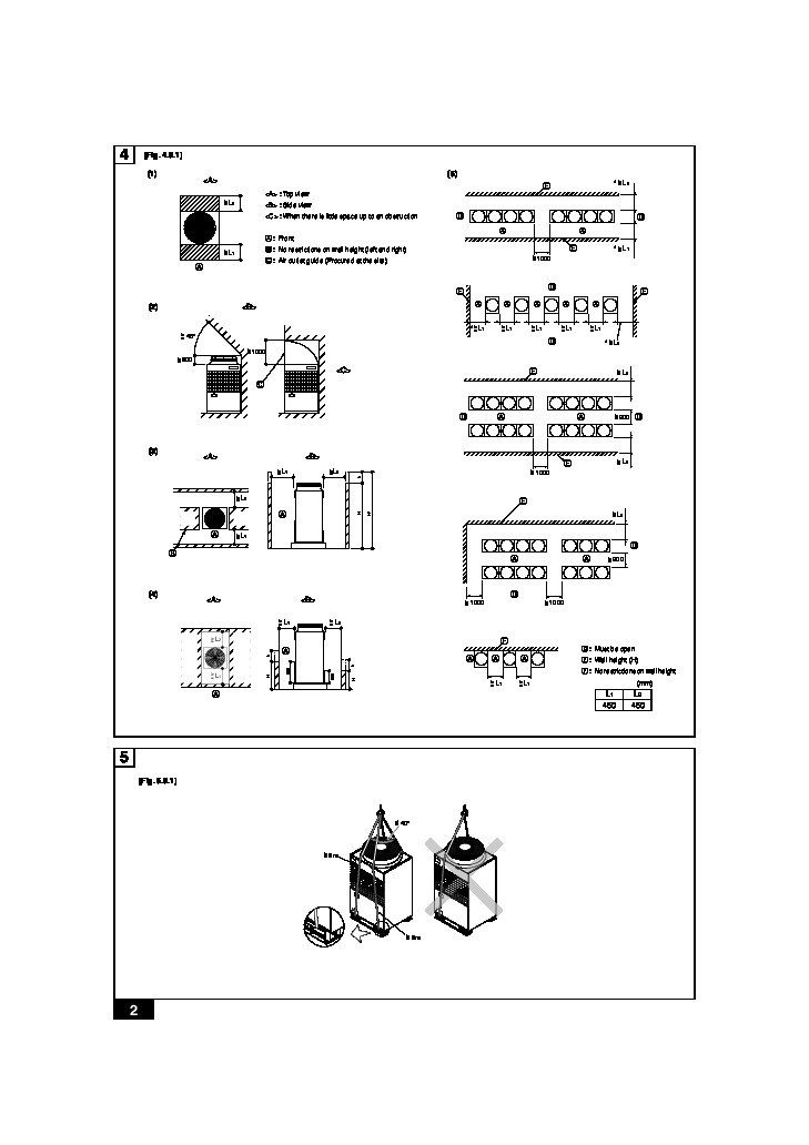
Air-Conditioners OUTDOOR UNIT PUHZ-8,10WYB For use with R410A GB INSTALLATIONthis installation manual thoroughly before installing the air-conditioner unit. MANUAL For safe and correct use, please read 4 [Fig. 4.0.1] (1) : Top view > = L2 (5) E : Side view : When there is little space up to an obstruction A : Front > = L1 * > L2 = D A A D B : No restrictions on wall height (left and right) C : Air outlet guide (Procured at the site) >
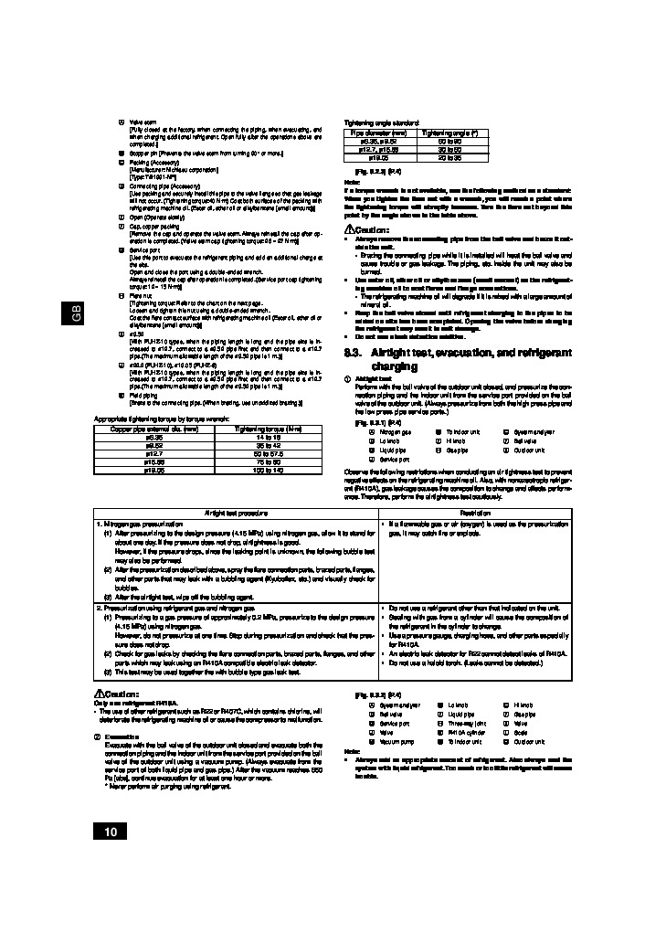
5.0.1] < 40° = < = 8m < 8m = 2 6 [Fig. 6.1.1] B A : M10 anchor bolt procured at the site. A B : Corner is not seated. 7 [Fig. 7.2.1] 7.2 A A : Outdoor unit B : Indoor unit a B (mm) Outdoor 8HP 10HP *1 ø12.7 for over 90m Liquid pipe ø9.52 *1 ø9.52 Gas pipe ø19.05 ø22.2 3 8 [Fig. 8.2.1] [Fig. 8.2.2] 8.2 A 3 [Ball valve (gas side/flanged type)] [Ball valve (liquid side)] This figure shows the valve in the fully open state. E E 1 B B A : Close-packed packing B : Hollow packing [Fig. 8.2.3] J (In case of PUHZ-10) (In case of PUHZ-8) A : Valve stem B : Stopper pin C : Packing (Accessory) D : Connecting pipe (Accessory) E : Open (Operate slowly) F : Cap, copper packing G : Service port H : Flare nut I : ø9.52 J : ø22.2 (PUHZ-10), ø19.05 (PUHZ-8) K : Field piping L : Joint pipe (Accessory) 8.3 [Fig. 8.3.1] F B B C A C LO A : Nitrogen gas [Fig. 8.3.2] D N E F A : System analyzer B : Lo knob C : Hi knob D : Ball valve E : Liquid pipe F : Gas pipe G H I HI B : To indoor unit C : System analyzer D : Lo knob E : Hi knob F : Ball