


3
Setup and
Adjustments
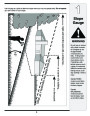
NOTE: The units illustrated may vary slightly from your
unit.
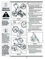
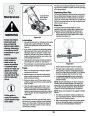
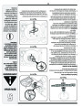
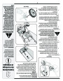
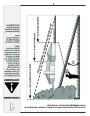
1.
Remove loose parts and any packing material which
may be between upper and lower handles.
a. Pull up and back on the upper handle to raise the
handle from position A into the operating position
B. See Figure 3-1.
A
b. Tighten knobs securing upper handle to lower
handle. Make sure that each carriage bolt is
seated properly in the handle.
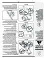
Locateside of lowerhairpinhandle.clip in one hole on the weld pin on each
2.
a. Remove hairpin clip from this hole. Using a pair of
pliers, insert hairpin clip into the other hole on the
weld pin. Repeat on other side.
B
b. Place one carriage bolt (found in the hardware
pack included with your unit) in the upper hole of
the right handle mounting bracket from the inside
outward. See Figure 3-2. Secure with one wing
nut. Repeat process on the left side.
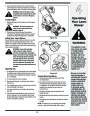
WARNING
Figure 3-1
Disconnect and
ground the spark
plug wire as instruct-
ed in the separate
engine manual.
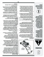
3.
4.
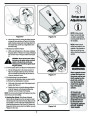
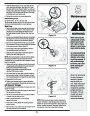
Rope guide Setup as follows, see Figure 3-3:
a. HoldPositiontheA.blade control against the upper handle.
b. Slowly pull starter rope out of engine. Position B.
c. Slip starter rope into the rope guide. Position C.
d. Tighten rope guide wing nut. Position D.
Insert post on cable ties into holes provided on the
lower handle. Pull cable tie tight and trim excess. See
Figure 3-4.
B
NOTE: This Operator’s
Manual covers
A
several models. Lawn
Mower features vary by
model. Not all features
discussed (or engines
pictured) in this manual
are applicable to all
Lawn Mower models.
Figure 3-2
A
Figure 3-4
IMPORTANT
This unit is shipped
WITHOUT GASOLINE
or OIL. After assem-
bly, service engine
with gasoline and
oil as instructed in
the separate engine
manual packed with
your unit.
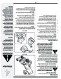
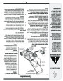
5. Each wheel has a height adjustment lever to change
the cutting height of the mower. To change the height
of cut, squeeze adjuster lever toward the wheel,
B
moving up or down to selected height. See Figure 3-5.
D
6.
To assemble the grasscatcher:
a. Place bag over frame (black plastic side is the
bottom of bag.) Insert the hooks on the frame
through the holes in the side plastic channels of
the bag. See Figure 3-6.
C
Figure 3-3
6
| Categories | Lawn Mower Manual, MTD Lawn Mower Manuals, Troy-Bilt Lawn Mower Manuals |
|---|---|
| Tags | MTD 560, Troy-Bilt 560 |
| Download File |
|
| Document Type | Owner's Manual |
| Language | English |
| Product Brand | MTD, Lawn Mower |
| Document File Type | |
| Publisher | mtdproducts.com |
| Wikipedia's Page | MTD Products |
| Copyright | Attribution Non-commercial |
(0 votes, average: 0 out of 5)