


MAINTENANCE AND REPAIR INSTRUCTIONS
NOTE: Maintenance, replacement, or repair of the emission control
devices and system may be performed by any non-road engine
repair establishment, individual or authorized service dealer.
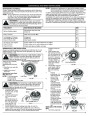
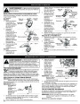
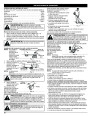
MAINTENANCE SCHEDULE
Perform these required maintenance procedures at the frequency
stated in the table. These procedures should also be a part of any
seasonal tune-up.
NOTE: Some maintenance procedures may require special tools
or skills. If you are unsure about these procedures take
your unit to any non-road engine repair establishment,
individual or authorized service dealer.
In order to assure peak performance of your engine, inspection of the
engine exhaust port may be necessary after 50 hours of operation. If
you notice lost RPM, poor performance or general lack of
acceleration, this service may be required. If you feel your engine is in
need of this inspection, refer service to any non-road engine repair
establishment, individual or authorized service dealer for repair. DO
NOT attempt to perform this process yourself as engine damage may
result from contaminants involved in the cleaning process for the port.
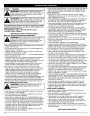
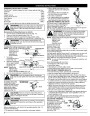
WARNING:
To prevent serious injury, never perform
maintenance or repairs with unit running. Always service
and repair a cool unit. Disconnect the spark plug wire to
ensure that the unit cannot start.
FREQUENCY
MAINTENANCE REQUIRED
SEE
Fill fuel tank with fresh fuel
Check oil
p. 5
p. 8
Before starting engine
Every 10 hours
Clean and re-oil air filter
p. 9
1st change at 10 hours
2nd change at 25 hours
Every 25 hours after
Change oil
p. 8
Change oil
p. 8
Clean spark arrestor
p. 10
10
Every 25 hours
Every 25 hours
hours on new engine
Check rocker arm to valve clearance and adjust
Check rocker arm to valve clearance and adjust
Check spark plug condition and gap
p. 9
p. 9
p. 10
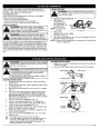
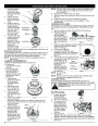
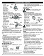
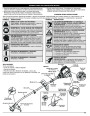
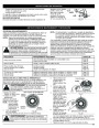
SPEEDSPOOL® LINE INSTALLATION
inserting it into the
eyelet.
Always use original equipment manufacturer 0.095 inch (2.41 mm)
replacement line. Lines other than those specified may make the
engine overheat or fail.
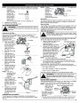
5.
Insert the line into
the locking hole (Fig.
22).
Do not push the
WARNING:
Do not remove or alter the line cutting
line more than a 1/2
inch (12.7 mm) into
the line locking hole.
The line will form a
small loop (Fig. 22)
when it is inserted
correctly.
blade assembly. Excessive line length will make the
clutch overheat. This may lead to serious personal
injury or damage to the unit.
Top View Of The SpeedSpool®
Arrows
Spool
There are two methods
to replace the
Line Locking Hole
Fig. 22
Outer
SpeedSpool® trimming
line:
6.
Pull the line from the
outer spool until the
line is tight against
the inner reel (Fig.
23).
•
•
Wind the inner reel with
new line
Install a pre-wound
inner reel
7.
8.
Repeat
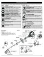
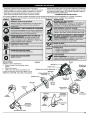
Winding the Inner Reel
With New Line
procedures 4-6
with the second
piece of line.
Bump
Knob
NOTE: It Is unnecessary
Inner Reel
to remove the
Fig. 20
Hold the outer
spool. Wind the
inner reel
bump knob to
install a new trimming line.
Fig. 23
WARNING: Do not remove or alter the line cutting
blade assembly. Excessive line length will make the
clutch overheat. This may lead to serious personal
injury or damage to the unit.
counterclockwise
until approximately
four (4) inches (102
mm) of line remain
(Fig. 24).
If winding the line
becomes difficult
or if the line jams,
pull the ends of
the line from the
spool (Fig. 24).
1.
2.
Cut two pieces of
inch (2.41 mm)
trimming line, 10 feet
m) long.
Trimming Line
Eyelet
9.
0.095
(3
Hold the outer spool
and turn the inner
reel
Fig. 24
Continue winding
the inner reel
counterclockwise
until approximately
counterclockwise to
line up the arrows on
the outer spool and
inner reel (Fig. 20).
Line Loading Hole
Fig. 21
6
inches of line is
3.
4.
Pull old line out of
the line loading and line locking holes (Fig. 22 and 23).
Insert a piece of trimming line straight into one of the two
eyelets in the outer spool. Push it up through the line loading
hole in the inner reel (Fig. 21). Do not bend the line when
left.
INSTALLING A PRE-WOUND
REEL
Turn the bump knob
1.
Fig. 25
7
| Categories | Lawn Mower Manual, MTD Lawn Mower Manuals, MTD Trimmer Manuals, Trimmer Manuals, Troy-Bilt Lawn Mower Manuals |
|---|---|
| Tags | MTD TB525CS, MTD TB575SS, Troy Bilt TB575SS, Troy-Bilt TB525CS |
| Download File |
|
| Document Type | Owner's Manual |
| Language | English |
| Product Brand | MTD, Lawn Mower |
| Product Type | Walk Behind Mower |
| Document File Type | |
| Publisher | mtdproducts.com |
| Wikipedia's Page | MTD Products |
| Copyright | Attribution Non-commercial |
(0 votes, average: 0 out of 5)