


en
ASSEMBLY
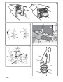
5. Install the fasteners and the crank assembly
eyebolt (11) that were removed in step 2.
DO NOT tighten until all fasteners are in
place.
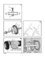
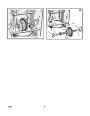
6. (Figure 5) Attach the crank rod (15) to the
universal joint assembly (16) with the hair
pin (12).
7. (Figure 4) Tighten nut on eye bolt (11).
Make sure eye bolt (11) is properly aligned
and the crank (18) can freely rotate.
How To Assemble The Drift Cutter
(if equipped)
Read and follow the assembly and adjustment
instructions for your snow thrower. All fasteners
are in the parts bag. Do not discard any parts or
material until the unit is assembled.
Drift cutters are used to cut a path through snow
deeper than the auger housing.
1.
(Figure 11) Loosen the fasteners (2) that
secure the drift cutters (1) to the auger
housing.
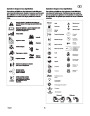
WARNING: Before doing any
assembly or maintenance to the
snow thrower, remove the wire
from the spark plug.
2.
3.
Raise the drift cutters (1) to the desired
height.
Tighten the fasteners (2).
NOTE: In this instruction book, left and right
describe the location of a part from the
operator’s position behind the unit.
NOTE: Torque is measured in foot pounds
(metric N.m). This measurement describes
how tight a nut or bolt must be. The torque is
measured with a torque wrench.
8. Tighten all handle fasteners.
How To Prepare The Engine
NOTE: The engine was shipped from the
factory filled with oil. Check the level of the
oil. Add oil as needed.
How To Install The Knob(s) (Figure 6)
NOTE: If knob(s) are already installed, go to
the next selection.
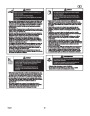
WARNING: Follow the engine
manufacturer’s instructions for the
type of fuel and oil to use. Always
use a safety fuel container. Do not smoke
when adding gasoline to the engine. When
inside an enclosure, do not fill with
gasoline. Before you add fuel, stop the
engine. Let the engine cool for several
minutes.
Check the oil. See the engine manufacturer’s
instructions for the type of fuel and oil to use.
Before you use the unit, read the information on
safety, operation, maintenance, and storage.
1.
2.
Attach the knob (3) onto the speed shift
lever (2). On some models, the knob (3)
is attached. To lock in position, tighten the
hex jam nut (1) against the bottom of the
knob (3).
Make sure the speed shift lever (2)
functions correctly. Move the speed shift
lever (2) through all speeds.
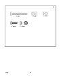
NOTE: Fasteners and loose parts are shown
at full size in Figure 2 on page 32.
NOTE: Illustrations are located on page 2
and on pages 33 through 38.
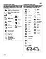
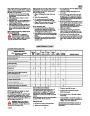
Tools Required
1
1
2
2
2
1
1
1
1
Knife
Pliers
How To Assemble The Chute Deflector
1/2 inch open end wrenches
9/16 inch open end wrenches
3/4 inch open end wrenches
Measuring tape or ruler
Screwdriver
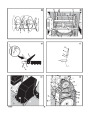
NOTE: The chute ring assembly (1) comes
installed on the unit from the factory (see
Figure 7).
Important! Before You Start Operating
Check the fasteners. Make sure all
fasteners are tight.
1.
2.
3.
Turn crank assembly (18, Figure 4) until
the arrow on outer ring (2, Figure 7) of
chute ring assembly points forward.
3/8 inch open end wrench
7/16 inch open end wrench
On electric start models, the unit was
shipped with the starter cord plugged
into the engine. Before operating,
Place chute ring (3) onto outer ring (2)
so the slot in the chute ring aligns with
the arrow on the outer ring.
How To Remove The Snow Thrower
From The Carton
unplug the starter cord from the engine.
Install chute deflector (4) using four screws
1.
2.
3.
4.
5.
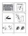
(Figure 3) The snow thrower is shown in the
OPERATION
(5)
and nuts (6) in holes as shown. The chute
shipping position.
deflector must point forward for proper
installation.
Remove packing material from wheels,
handle, and auger housing.
Locate and remove the parts bag (some
models do not have a parts bag).
Cut open the end of the carton next to the
handle.
To roll the snowthrower off of the carton, pull
on the handle.
NOTE: Illustrations are located on page 2
and on pages 33 through 38.
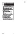
CAUTION: Use only attachments and
accessories approved by the manufacturer
of the snow thrower (such as tire chains,
electric start kits, etc.).
4. Tighten screws snugly but be careful not to
over-tighten.
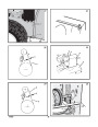
Check The Cables
1.
(Figure 8) Check the traction drive cable
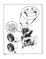
Know Your Snow Thrower (Figure 1)
(1)
and the auger drive cable (2). If the
Read this Instruction Book and safety rules
before operation the snow thrower. Compare the
illustration with your snow thrower to familiarize
yourself with the location of various controls and
adjustments.
CAUTION: DO NOT back over cables.
Remove any packing material that remains
from handle and auger housing.
Cut orange plastic shipping ties that may
secure the control cables to the LOWER
HANDLE.
bottom of the cables have become
disconnected, reinstall the cables.
6.
7.
2.
(Figure 10) If the top of the cables (5) have
become disconnected from the drive
levers (6), attach the cables (5) to the “Z”
fitting (7).
How To Control The Discharge Of
The Snow
8.
If the control cables have become
disconnected from the control levers, then
attach the cable to the levers (see Owner’s
Manual for illustration of cable and lever).
How To Set The Skid Height (Figure 1)
WARNING: Never direct the
discharge of snow toward
bystanders.
The snow thrower is equipped with height
adjustable skids (7) mounted on the outside of
the auger housing (4). To adjust the height of
the skids, see “How To Adjust The Height Of
The Skids” in the Maintenance section.
How To Assemble The Handle And
Crank Assembly
WARNING: Always stop the engine
before unclogging the discharge
chute or the auger housing and
1.
(Figure 4) Loosen, but do not remove, the
fasteners (1) in the upper holes of the lower
handle.
before leaving the snow thrower.
How To Set The Length Of The Cables
1.
(Figure 1) Turn the crank assembly (2) to
change the discharge direction of the snow.
2.
Remove the fasteners and the crank
assembly eyebolt (11) from the lower holes
of the lower handle.
The cables were adjusted at the factory and no
adjustments should be necessary. However,
after the handles are put in the operating
position, the cables can be too tight or too loose.
If an adjustment is necessary, see “How To
Check And Adjust The Cables” in the Service
And Adjustment section.
2. (Figure 12) Loosen the wing knob (1) on
the chute deflector (2) and move the chute
deflector (2) to set the distance. Move the
chute deflector (2) UP for more distance,
DOWN for less distance. Then tighten the
wing knob (1).
3.
4.
(Figure 1) Put the shift lever (6) into first
forward position.
(Figure 4) Raise the upper handle (2) to the
operating position.
NOTE: Make sure the cables are not
caught between the upper and lower
handle.
1
742237
9
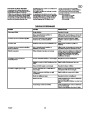
| Categories | Murray Snow Blower Manuals, Snow Blower Manuals |
|---|---|
| Tags | Murray 1695539 |
| Download File |
|
| Document File Type | |
| Copyright | Attribution Non-commercial |
(1 votes, average: 5 out of 5)
Lawn and Garden readers have rated Murray Walk Behind 1695539 8.0 24-Inch Dual Stage Snow Blower Owners Manual 5.0 out of 5.0 based on 1 product reviews. very good snowblover