| Categories | Agricultural Equipment and Harvesting Machinery Manuals, New Holland Agricultural Equipment Manuals |
|---|---|
| Download File |
|
| Document File Type | |
| Copyright | Attribution Non-commercial |
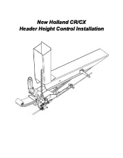
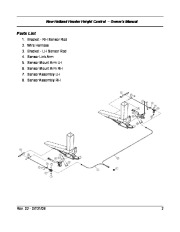
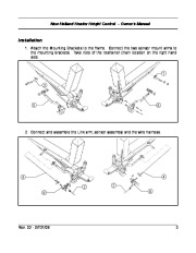
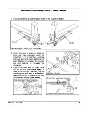
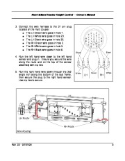
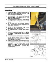
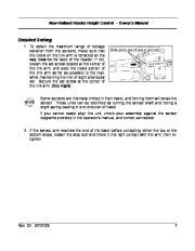
New Holland CR/CX Header Height Control Installation New Holland Header Height Control Owner’s Manual New Holland Header Height Control Introduction The Header Height Control system is greatly affected by the other settings on the header. For this reason, it is critical to the correct operation of the Header Height Control that it be adjusted after the header is prepared for the crop conditions that exist in your location.
Agricultural Equipment Manual Free Download. Lawn Mowers Specs. Power Harvesting Machinery Free Specification Download PDF.
To achieve this, it must be set up in the shop simulating these operating parameters, or in the field under actual operating conditions. The header must be lowered into the cutting position, with the proper amount of weight on the gauge wheels and with the cutting angle set. Since the header tilt changes the header’s center of gravity and cutting angle, adjustments to the header tilt will affect the deflection of the suspension springs, which in turn will affect the calibration of the height sensor. Make sure that the cutting angle is properly set. Refer to the Operator’s Manual. Ensure the header is level, the cutter bar is at a good height for most crops, and that the mounting points, restrainer chains and lift link bolts are set correctly. When you are satisfied that the header is physically set up, study these instructions, then install and calibrate the Header Height Control. The header height control system uses different sensors for each make of combine, therefore the sensors you see in the illustrations in this manual may not appear to be the same as those that arrived in your kit. Terminology The following diagram illustrates the important components and the terms used for them in this installation guide. Sensor Sensor Arm Rev. 02 – 07/31/08 Clevis & Pin Pivot Arm Link Arm Set Screw Bracket 1 New Holland Header Height Control Owner’s Manual Parts List 1. Bracket – RH Sensor Rod 2. Wire Harness 3. Bracket – LH Sensor Rod 4. Sensor Link Arm 5. Sensor Mount Arm LH 6. Sensor Mount Arm RH 7. Sensor Assembly LH 8. Sensor Assembly RH Rev. 02 – 07/31/08 2 New Holland Header Height Control Owner’s Manual Installation 1. Attach the Mounting Brackets to the frame. Connect the two sensor mount arms to the mounting brackets. Take note of the restrainer chain location on the right hand side. 1 3 5 6 2. Connect and assemble the Link arm, sensor assembly and the wire harness. 4 2 8 2 8 4 Rev. 02 – 07/31/08 3 New Holland Header Height Control Owner’s Manual 1. Ensure everything is assembled as shown in the illustration below. Pivot Pivot Header Height Control Fully Assembled 2. Check the pivot to ensure it does not bind and has adequate room for movement. If it is restricted, unscrew the pivot point and install additional ½ ” SAE Washers in between the coupler nut and bearing to increase the clearance. 3. Ensure the Clevis and Pin rotate freely and do not bind (See Lower Right). If there is not enough clearance, pry the clevis slightly apart with a screwdriver. Make sure the pin is located in the rear of the sensor arm slot (See Below). Slide pin to rear of sensor arm slot. Adding a Washer Ensure there is adequate clearance Link Arm and Sensor Arm Top View Rev. 02 – 07/31/08 4 New Holland Header Height Control Owner’s Manual 3. Connect the wire harness to the 31 pin plug located on the multi coupler. The LH Green wire goes in hole 1. The LH White wire goes in hole 23. The LH Black wire goes in hole 25. The RH Green wire goes in hole.
