


The Indicator Monitor will also remind the operator of
maintenance intervals for changing the engine oil. The
LCD will alternately flash, “CHG” ; “OIL” and the recorded
hours for five minutes after every 50 hours of recorded
operation. The maintenance interval lasts for two hours
(from 50-52, 100-102, 150-152, etc.). The LCD will flash as
described for five minutes every time the tractor’s engine
is started during this maintenance interval. Follow the oil
change intervals provided in the engine manual.
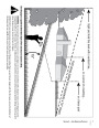
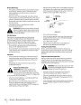
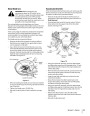
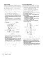
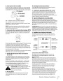
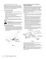
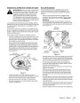
This symbol indicate
the Choke position
CHOKE
This symbol indicate
the fast position
This symbol indicates
the slow position
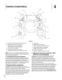
Figure 4-5
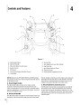
Indicator Panel Features
•
Push the throttle control handle forward to increase the
engine speed. The tractor is designed to operate with
the throttle control in the fast position (full throttle)
when the tractor is being driven and the mower deck is
engaged.
Battery Indicator (Refer to Figure 4-4)
Illuminates and the battery voltage is displayed briefly
when the ignition switch it turned to the “ON” position.
Illuminates to indicate the battery voltage has dropped
below 11.5 (+0.5/-1.0) volts. The battery voltage is also
displayed on the hour meter. If this indicator and display
come on during operation, check the battery and charging
system for possible causes and/or contact your Troy-Bilt
dealer.
•
•
Pull the throttle control handle rearward to decrease
the engine speed.
When starting the engine, push the control handle
fully forward into the “CHOKE” position. Refer to Figure
After starting and warming the engine, move the
4-5.
Oil Pressure Indicator (Refer to Figure 4-4)
This warning lamp indicates low engine oil pressure. If the
indicator comes on while the engine is running, stop the
engine immediately and check for possible causes. Do not
run the engine while this indicator is illuminated. Contact
your Troy-Bilt dealer to have the tractor and engine
inspected.
control handle rearward until you feel it move past the
choke detent..
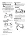
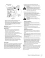
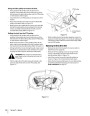
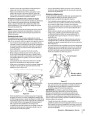
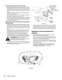
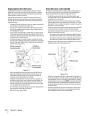
O. Parking Brake Engagement Lever
The parking brake engagement lever is located on the
front/left of the seat box frame, and is used to engage the
parking brake.
NOTE: The oil pressure indicator may illuminate when the
ignition switch is in the ON position, but should turn off when
the engine is started.
Pull the lever fully upward and to the left; then lower into
the short “J” slot to engage the brake.
Pull the lever up out of the “J” slot and to the right; then
lower completely to disengage the parking brake.
PTO Engaged Indicator (Refer to Figure 4-4)
IMPORTANT: If the LH and RH drive control levers are not
fully opened out in the neutral position when engaging
the parking brake, the engine will stop. The parking brake
must be placed in the engaged position when starting the
tractor engine.
This indicator illuminates when the PTO switch is pulled
upward in the “ENGAGED” position and the ignition switch
is turned to the “START” position. Check this indicator if
the engine will not crank with the ignition switch in the
“START” position. If necessary, move the PTO switch to the
“DISENGAGED” position.
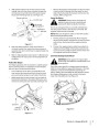
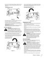
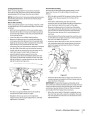
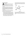
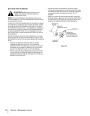
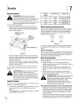
Rear Bumper (Not Shown)
Parking Brake Engaged Indicator (Refer to Figure 4-4)
The tractor is equipped with a removable rear bumper. The
rear bumper provides protection to the rear of the tractor
frame and engine during turns.
This indicator illuminates when the parking brake is in the
DISENGAGED position and the ignition switch is turned to
the “START” position. Check this indicator if the engine will The rear bumper must be removed from the tractor when
not crank with the ignition switch in the “START” position.
If necessary, move the parking brake to the ENGAGED
position.
installing a Rear Bagger Kit. Or you may want to remove
the bumper to reduce the over-all length of the tractor. To
Remove the rear bumper, proceed as follows:
This indicator also illuminates when the ignition switch is
turned to the “START” position and the RH and/or LH drive
control levers are in a position other than the fully out in
neutral position. Move the control levers fully outward.
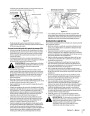
•
From the inside surface of the tractor frame, just
rearward of the rear tire on either side of the tractor,
pull the internal cotter pin from the clevis pin. Move to
the other side of the tractor and remove the internal
cotter pin from the other clevis pin. Refer to Figure 3-4
if necessary.
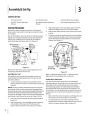
M.Throttle Control
The throttle control is located on the LH console to the
left of the operator’s seat. When set in a given position, a
uniform engine speed will be maintained. Refer to Figure
4-5.
•
While supporting the rear bumper, withdraw the clevis
pin from both sides of the bumper, and pull the rear
bumper rearward off of the tractor frame.
1
sectiOn 4— cOntrOls and features
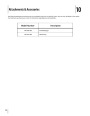
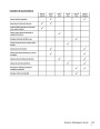
| Categories | Lawn Mower Manual, MTD Lawn Mower Manuals, Troy-Bilt Lawn Mower Manuals |
|---|---|
| Tags | MTD RZT, Troy-Bilt RZT |
| Download File |
|
| Document Type | Owner's Manual |
| Language | English |
| Product Brand | MTD, Lawn Mower |
| Document File Type | |
| Publisher | mtdproducts.com |
| Wikipedia's Page | MTD Products |
| Copyright | Attribution Non-commercial |
(0 votes, average: 0 out of 5)