


3
.
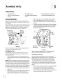
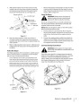
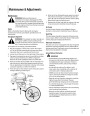
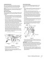
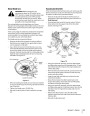
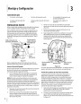
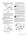
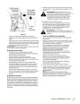
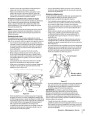
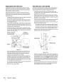
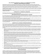
Slide the flat washer onto the hex screw. From the
outside, insert the hex screw w/washer through the
control lever slot and the hole of the pivot bracket.
Secure with the flange lock nut. See Figure 3-3.
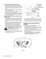
•
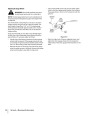
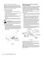
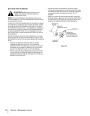
Remove the bumper and reposition to align the notch
at each end of the bumper with the spacer on each
side of the frame. Slide the bumper notches onto the
spacers. Refer to Figure 3-4.
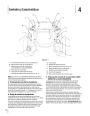
Connect the Battery
WARNING!: Battery posts, terminals and
Flange Lock Nut
Control Lever
related accessories contain lead and lead
compounds. Wash hands after handling.
Lift control
lever upward
The tractor is shipped with an activated sealed battery,
with the positive battery cable factory connected. The
negative cable must be connected.
Flat Washer
Hex Screw
Pivot
Bracket
NOTE: Make sure the ignition switch is in the “OFF” position
before attaching the battery cable.
1
.
Pull the protective cap (if present) off the negative
terminal of the battery, and remove the hex cap screw
and nut from the free end of the negative battery
cable.
Slotted
Hole
Figure 3-3
2
.
Connect the negative battery cable (heavy black) to
negative terminal (NEG) of the battery using the hex
cap screw and nut. Slide the black terminal cover over
the negative terminal of the battery.
4
5
.
.
Note the relative position of the control lever to
the pivot bracket, then repeat the previous steps to
reposition the other control lever in approximately the
same position.
Refer to “Adjusting Drive Control Levers” in Maintenance
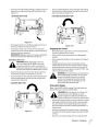
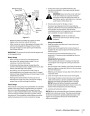
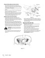
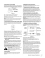
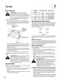
Lower Deck Discharge Chute Deflector
&
Adjustments for instructions on final adjustment of
the levers.
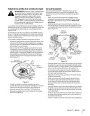
WARNING!: Never operate the mower deck
without the chute deflector installed and in the
down position.
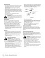
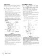
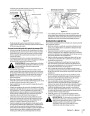
Position Rear Bumper
For shipping purposes the rear bumper is rotated upward
from its normal position. To reposition the rear bumper,
refer to Figure 3 and proceed as follows:
Check the mower deck for a shipping brace (w/tag) that
holds the chute deflector upward for shipment. If a brace
is present, it must be removed before operating the
tractor. Holding the chute deflector fully upward, remove
the shipping by grasping it and rotating it clockwise.
Lower the chute deflector. See Figure 3-5.
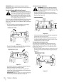
•
From inside the tractor frame, just behind the rear
tires, remove the internal cotter pins from the clevis
pins securing the bumper to each side of the frame.
•
While supporting the rear bumper, cut the cable tie
fastening the bumper to the engine lift bracket, and
remove the clevis pins from each side. See Figure 3-4.
Notch
Shipping
Brace
Clevis Pin
Internal
Spacer
Figure 3-4
Figure 3-5
Cotter Pin
sectiOn 2 — asseMbly & set-up
9
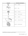
| Categories | Lawn Mower Manual, MTD Lawn Mower Manuals, Troy-Bilt Lawn Mower Manuals |
|---|---|
| Tags | MTD RZT, Troy-Bilt RZT |
| Download File |
|
| Document Type | Owner's Manual |
| Language | English |
| Product Brand | MTD, Lawn Mower |
| Document File Type | |
| Publisher | mtdproducts.com |
| Wikipedia's Page | MTD Products |
| Copyright | Attribution Non-commercial |
(0 votes, average: 0 out of 5)