


ENGLISH
ASSEMBLY
NOTE: Make sure the cables are not
caught between the upper and lower han-
dle.
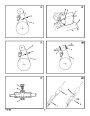
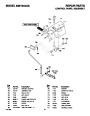
Check The Cables
1.
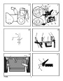
(Figure 5) Check the traction drive cable
(1) and the auger drive cable (2). If the bot-
Read and follow the assembly and adjustment
instructions for your snow thrower. All fasteners
are in the parts bag. Do not discard any parts or
material until the unit is assembled.
5. Install the fasteners that were removed in
step 2. DO NOT tighten until all fasteners are
in place.
tom of the cables have become discon-
nected, reinstall the cables.
2. (Figure 6) If the top of the cables (5) have
become disconnected from the drive levers
6.
Tighten all handle fasteners.
WARNING: Before doing any
assembly or maintenance to the
snow thrower, remove the wire
from the spark plug.
(6), attach the cables (5) to the “Z” fitting
(7).
How To Install The Knobs
NOTE: If knobs are already installed, go to
the next selection.
How To Set The Skid Height (Figure 2)
NOTE: In this instruction book, left and right
describe the location of a part from the oper-
ator’s position behind the unit.
The snow thrower is equipped with height ad-
justable skids (7) mounted on the outside of the
auger housing (4). To adjust the height of the
skids, see “How To Adjust The Height Of The
Skids” in the Maintenance section.
NOTE: Torque is measured in foot pounds
(metric N.m). This measurement describes
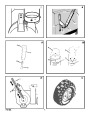
Remote Chute Knob
how tight a nut or bolt must be. The torque is 1. (Figure 9) Assemble remote chute knob (1)
measured with a torque wrench.
onto lever (2) until snug against nut (3). On
some models the remote chute knob (1) is
attached.
How To Assemble The Drift Cutter
(if equipped)
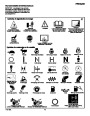
NOTE: Illustrations begin on page 3.
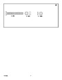
NOTE: Fasteners and loose parts are shown
at full size in Figure 25.
2.
3.
Make sure lip (4) on the remote chute knob
Drift cutters are used to cut a path through snow
deeper than the auger housing.
(1)
is pointed toward the engine.
Tighten the nut (3) against the bottom of the
1.
(Figure 11) Loosen the wingnuts (2) that
secure the drift cutters (1) to the auger
housing.
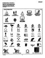
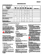
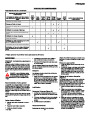
Tools Required
remote chute knob (1).
1
1
2
2
2
1
1
Knife
2.
3.
Raise the drift cutters (1) to the desired
height.
Tighten the wingnuts (2).
Pliers
Speed Select Knob
1/2 inch open end wrenches
9/16 inch open end wrenches
3/4 inch open end wrenches
Measuring tape or ruler
Screwdriver
1.
(Figure 9) Install the speed select knob (1)
to the speed select lever (2) until snug
against nut (3). On some models the speed
select knob (1) is attached.
How To Prepare The Engine
Note: The engine was shipped from the fac-
Make sure lip (4) on the remote chute knob tory filled with oil. Check the level of the oil.
(1) is pointed toward the engine.
2.
3.
Add oil as needed. Engine does not contain
GASOLINE.
Tighten the nut (3) against the bottom of the
remote chute knob (1).
How To Remove The Snow Thrower
From The Carton
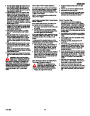
WARNING: Follow the engine
manufacturer’s instructions for the
type of fuel and oil to use. Always
use a safety fuel container. Do not smoke
when adding gasoline to the engine. When
inside an enclosure, do not fill with gaso-
line. Before you add fuel, stop the engine.
Let the engine cool for several minutes.
1.
2.
3.
4.
5.
6.
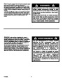
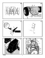
(Figure 1) The snow thrower is shown in the
shipping position.
How To Install The Speed Control Rod
(Figure 9) Put the speed select lever (6) in
the NEUTRAL position.
1.
Cut and discard the plastic tie that secures
the crank assembly.
2.
(Figure 24) Attach the ball joint (1), located
on the bottom end of the speed control rod
Cut down all four corners of the carton and
lay the side panels flat.
(2),
to the shift yoke assembly (3). The fas-
Check the oil. See the engine manufacturer’s
instructions for the type of fuel and oil to use.
Before you use the unit, read the information on
safety, operation, maintenance, and storage.
Locate all parts that are packed separately
and remove from the carton.
teners (4) are attached to the ball joint (1)
at the factory.
Remove and discard the packing material
from around the snow thrower.
3.
The length ot the ball joint (1) and speed
control rod (2) have been pre-adjusted at
the factory. If an adjustment is required, loos-
en the nut (5). Remove the fasteners (4) to
disconnect the ball joint (1) from the shift
yoke assembly (3). To lengthen or shorten
the speed control rod (2), turn the adapter
(7) to obtain the correct length.
(Figure 2) For shipping purposes, the height
adjust skids (7) are attached to the pallet.
Remove the screw (17) that secures each
height adjust skid (7) to the pallet.
Important! Before You Start Operating
r
r
Check the fasteners. Make sure all fas-
teners are tight.
7.
Hold onto the lower handle and pull the snow
thrower off the pallet.
On electric start models, the unit was
shipped with the starter cord plugged
into the engine. Before operating, un-
plug the starter cord from the engine.
CAUTION: DO NOT back over cables.
4. (Figure 9) Make sure the speed select lever
(6) functions correctly. Move the speed se-
lect lever (6) through all speeds.
8.
9.
Remove the packing material from the han-
dle assembly.
Cut the ties that secure the clutch control
cables (1) to the lower handle (2). Move the
cables away from the motor frame.
r
If a bar code label is attached to the han-
dle, remove before operating.
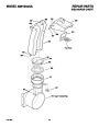
How To Assemble The Chute Deflector
1.
2.
(Figure 10) Remove carriage bolt (1).
Raise the chute deflector (2) into operating
position (3).
OPERATION
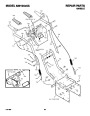
How To Assemble The Handle
1.
(Figure 3) Loosen, but do not remove, the
fasteners (1) in the upper holes of the lower
handle (3).
3.
Fasten chute deflector (2) to flange (4) with
carriage bolt (1). Make sure to install with
the head of the carriage bolt (1) on the in-
side of the flange (2).
NOTE: Illustrations begin on page 3.
2.
3.
4.
Remove the fasteners from the lower holes
of the lower handle.
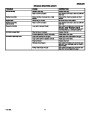
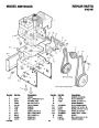
Know Your Snow Thrower (Figure 2)
4.
5.
Fasten with washer (5) and locknut (6).
Tighten locknut (6) securely.
Read this Instruction Book and safety rules be-
fore operation the snow thrower. Compare the
illustration with your snow thrower to familiarize
(Figure 2) Put the shift lever (6) into first
forward position.
(Figure 3) Raise the upper handle (2) to the NOTE: Make sure all carriage bolts in flange yourself with the location of various controls and
operating position.
F-031099L
are tight. DO NOT OVERTIGHTEN.
11
adjustments.
| Categories | Murray Snow Blower Manuals, Snow Blower Manuals |
|---|---|
| Tags | Murray 629104X5A |
| Download File |
|
| Document File Type | |
| Copyright | Attribution Non-commercial |
(0 votes, average: 0 out of 5)